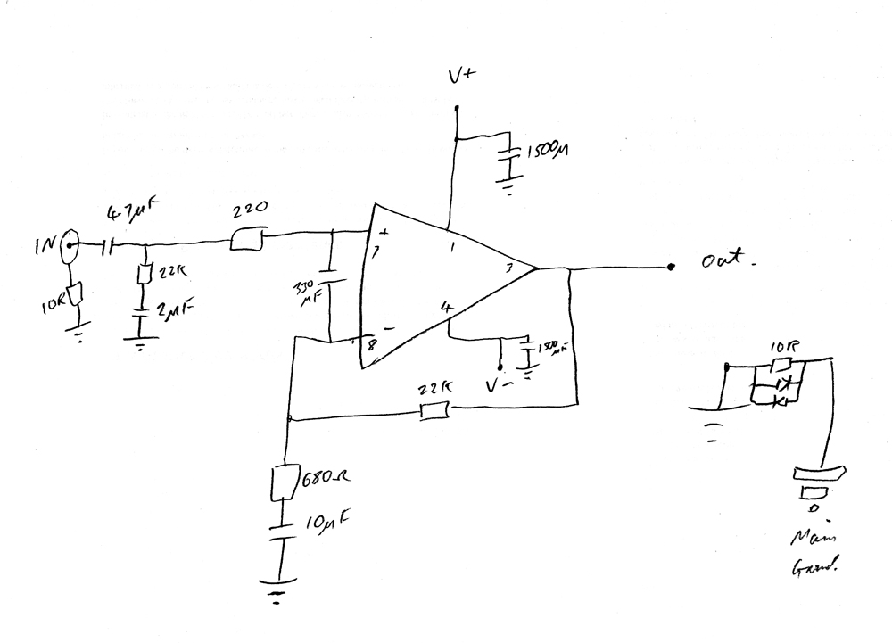
Make the 220 ohm resistor 1K. Put a 330pF after it to signal ground. 330uF between the input pins is wrong. Increase the 10uF in series with the 680 ohm resistor to 22uf
What is the 2uF in series with the 22K for? The input cap is also much too big - keep it to 10uF (or a 4.7uF polyester if you can get it).
Get some 100nF capacitors on the power supply rails, as close to the chip as you can.
What is the 2uF in series with the 22K for? The input cap is also much too big - keep it to 10uF (or a 4.7uF polyester if you can get it).
Get some 100nF capacitors on the power supply rails, as close to the chip as you can.
Hi Bill_P,
Sorry, my drawing has a mistake. There is a 330pF cap between + and - of the chip, I have written it wrong and the input cap is 4.7uF. My crappy drawing makes it look like a 47uF.
Anyway, I will change the other caps and resistor as you suggested and post back my findings
Thanks very much Bill_P
Sorry, my drawing has a mistake. There is a 330pF cap between + and - of the chip, I have written it wrong and the input cap is 4.7uF. My crappy drawing makes it look like a 47uF.
Anyway, I will change the other caps and resistor as you suggested and post back my findings
Thanks very much Bill_P
the 10uF in the NFB leg is sized so:
C >= 4.7uF * 22k / 680r * sqrt(2)
...>= 4.7 * 10^-6 * 22 * 10^3 / 680 * 1.414
...>= 0.000215F
...>= 215uF
use 220uF or 330uF.
The +IN pin and the -IN pin should each see similar DC resistance to ground to minimise output offset.
The +IN sees 22k+2uF // 4.7uF.
At DC both of these are effectively infinite resistance.
The -IN sees 680r+10uF // 22k. One route is infinite resistance, the other route is 22k.
The grounding capacitor, 2uF, on the +input must be removed. Then +IN sees 220r+22k
Last edited:
Right, so I now have this arrangement:
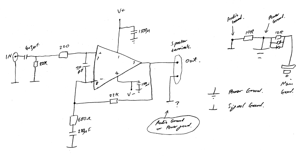
But is the -ve speaker output grounded to the power ground or the audio ground?
Sorry for all the dumb questions... (12 years as an electrical engineer, a few years of PIC programming experience doesn't seem to be helping with this analogue stuff!)
But is the -ve speaker output grounded to the power ground or the audio ground?
Sorry for all the dumb questions... (12 years as an electrical engineer, a few years of PIC programming experience doesn't seem to be helping with this analogue stuff!)
Electrolytic is fine. If you're finicky, you can use two 470uF caps connected back to back, or bypass the electrolytic with a small value (<1uF) Metallised Polypropylene capacitor. 220uF in any other fabrication than electrolytic is very diffuclt, expensive and not worth the investment for this application.
OK. I have applied the changes and yes the pop has gone. ")
(by the way I am using a very cheap £2 speaker that I found in the cupboard, don't wanna try it on my Monitor Audio speakers just yet....)
So this first demo GainClone now seems to work with my cheap speaker, and the DC offset read 0.7mV (with a 10 ohm resistor across the speaker output), but that's what the meter said.
I just built another the same, just so I can see what it would sound like in proper stereo, but when I put the 10 ohm (1 Watt) resistor across the output to take the DC offset, it frazzled. I quickly unplugged everything and checked the wiring, but everything seems fine, I tried it again and it was OK this time (0.8mV)! I can't work out why it burnt the resistor out the first time, the only thing that I think could have happened is that the output wire from the other Gainclone circuit may have touched the ground of the rca plug! Would this have caused this?
Anyway, I need to know what could have caused this as I wouldn't want to blow up my nice speakers.
Also, should the chips run warm even when there is no input connected or output?
power up through the bulb tester.
If something is mis-wired or shorted or oscillating and causes extra current draw then the bulb will light up and severely limit the power delivered to the transformer.
Do the output offset measurement with the input shorted and the output open circuit.
Repeat after connecting the source.
If something is mis-wired or shorted or oscillating and causes extra current draw then the bulb will light up and severely limit the power delivered to the transformer.
Do the output offset measurement with the input shorted and the output open circuit.
Repeat after connecting the source.
Hi Andrew,
Again, thanks for jumping on one of my threads and giving some advise. I found out why the resistor frazzled. The signal ground on that channel had a wire come off, which was the one connecting it to power ground via the 10 ohm resistor. My final amps that I make will be much better made than this experimental one.
It is slightly worrying that if this happened with a good set of speakers connected, that I could have burnt the coil of them out. Is there a way of protecting the speakers from this?
Anyway, later on tonight I will post back some results of the DC offset with source shorted, and also with source connected. I will also connect a scope to the output to see if there is any oscillation.
Thanks again everyone for your help
if that 10r resistor might, under fault conditions, have to pass a few or many amperes then it needs to be bypassed with two inverse parallel power diodes, 1n400x is good enough.
Close rated F fuses in the two supply rails should blow fast enough to save the speakers. They will be too slow to save the amplifier.
DC detect, triggering input mute and output relay is another way.
Close rated F fuses in the two supply rails should blow fast enough to save the speakers. They will be too slow to save the amplifier.
DC detect, triggering input mute and output relay is another way.
Hi again AndrewT,
I have a 10R paralleled with 2 x back to back diodes from the Power Ground to main earth.
I have a 10R from signal Ground to Power Ground. So adding 2 diodes to this resistor is also a good idea then?
I'll have a look into the fuses and the output relays.
Thanks again
I have a 10R paralleled with 2 x back to back diodes from the Power Ground to main earth.
I have a 10R from signal Ground to Power Ground. So adding 2 diodes to this resistor is also a good idea then?
I'll have a look into the fuses and the output relays.
Thanks again
I think the first time I saw it was on an MJL? schematic. It made me stop and think. Why?I have a 10R from signal Ground to Power Ground. So adding 2 diodes to this resistor is also a good idea then?
Then it dawned that a mains fault in another piece of equipment could send the voltage up the screen to the amp.
The diodes let the fault current pass to Safety Earth and hopefully the close rated fuse in the other equipment ruptures before anyone pulls out the plug to find out what has gone wrong.
- Status
- This old topic is closed. If you want to reopen this topic, contact a moderator using the "Report Post" button.
- Home
- Amplifiers
- Chip Amps
- Popping sound after turn off?