I am trying to sort out an Electrocompaniet (EC) AW-100 DMB amplifier and wanted to ask for help from the experts on this site.
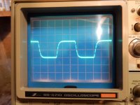
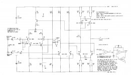
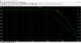
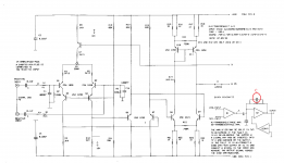
The idling current (bias) and the DC adjustments have been made to the manufacturer's recommendations. In use the amplifier lacks treble and is bass heavy. The first image shows the square wave response at 10kHz across a resistive load and the lack of high frequencies. EC will not give me the circuit diagrams to identify where filtering is taking place. However, they did say there was filtering in the input section. The second image is a circuit diagram found on the internet which appears to cover this amplifier.
I think the only filtering is due to C1 and C14 which at 1000pf seems too large. If this is correct, would I see any significant improvement by reducing it’s value to 47-100pf?
I would appreciate any comments or further suggestions if this is wrong.
Attachments
C1 and C14 1000pf will not make amplifier lacks treble / heavy bass, it must be some other reason caused.
for normal design 1000pf seems a little bit high, 330pf~47pf is reasonable
for normal design 1000pf seems a little bit high, 330pf~47pf is reasonable
Thanks for the replies. I have just removed an amplifier board and found that C1 and C14 are actually 100pf as one would expect.
I don't understand knutn's reply. Could you please identify the component?
I don't understand knutn's reply. Could you please identify the component?
It is hard to say if there is a technical issue with the amp. Most likely none. A frequency response sweep will help but I am more inclined to think it needs some general cap/relay/connector maintenance.
An OK response I would say, but it is presumably by carefully considered design. Extremely wide bandwidths and fast rise times are not always desirable.
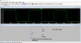
I can easily replicate the 10kHz signal on an amp simulation as here and this gives a -3db point of around 45kHz for a signal that looks like the actual scope shot.
I can easily replicate the 10kHz signal on an amp simulation as here and this gives a -3db point of around 45kHz for a signal that looks like the actual scope shot.
Attachments
I don't understand knutn's reply. Could you please identify the component?
A2 is the transresistance amplifier. You have only shown the transconductance amp A1. I have marked the capacitor in red.
Attachments
Thanks again for the replies.
My digital signal generator produces perfect square waves at 10kHz.
EC said they could see nothing wrong with the amplifier so it seems I will just have to get used to it.
Presumably, C is the C9, 220pf, capacitor in the feedback loop of the circuit I have available?
My digital signal generator produces perfect square waves at 10kHz.
EC said they could see nothing wrong with the amplifier so it seems I will just have to get used to it.
Presumably, C is the C9, 220pf, capacitor in the feedback loop of the circuit I have available?
The poles of the amp response will be normally be set by Miller capacitance in any common-emitter stage that's not cascoded. The slew-rate limit is also usually determined by Miller capacitance and drive current limits.
Is the slope independent of input amplitude? Then its slew limit, otherwise its frequency
response.
The small-signal bandwidth and large signal bandwidth will be different due to slew-rate
limiting.
Is the slope independent of input amplitude? Then its slew limit, otherwise its frequency
response.
The small-signal bandwidth and large signal bandwidth will be different due to slew-rate
limiting.
You can break the jumper and feed signal to the amp section to test the frequency
response ok or not. I think we can input a RCA pre-amp output to the power amp section to test it in real listening.
below maybe the power amp diagram and another is the 120 model with DC servo circuit for reference.
response ok or not. I think we can input a RCA pre-amp output to the power amp section to test it in real listening.
below maybe the power amp diagram and another is the 120 model with DC servo circuit for reference.
Attachments
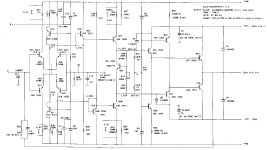

The lowest pole (roll off freq) is mostly determined by the stage with the most openloop amplification and the highest load resistance (not ment 'current load'). Often the socalled VAS-stage, here with Q9-Q11.
Can you show a picture how the signal looks at R13-R14? These are relative low impedance points and easy to measure.
If it looks the same, there's something with the first stage, otherwise with the Q9-Q11 stage.
Can you show a picture how the signal looks at R13-R14? These are relative low impedance points and easy to measure.
If it looks the same, there's something with the first stage, otherwise with the Q9-Q11 stage.
[ VAS stands for "voltage amplification stage", so "VAS-stage" is redundant 🙂 ]
I can't square that really, as a cascoded stage has a very different roll-off to a non-cascoded one for the same load resistance and open loop gain. Poles are due to time-constants, which are mainly due to the interplay of resistance and capacitances, and also to feedback paths formed by capacitances (effectively multiplying capacitance as with Miller cap)The lowest pole (roll off freq) is mostly determined by the stage with the most openloop amplification and the highest load resistance
Guys, I think this is an open loop amplifier. Meaning it is a GM on R amp.
Referring to the schematic on the first post.
The gain of this thing is GM_A1 x RF_A2.
- GM_A1 = ~1/2.25K
- RF_A2 is not labelled (the feedback R around A2).
Now, regarding BW, it will the minimum of:
- Input filter: R1=1k on C1=1000pF = 160KHz (thought I think op said C1=100pF, so then actually becomes 1.6MHz)
- GM_A1 on CF_A2, where CF is the feedback cap around A2, which is unlabeled.
@bkneale: Do you have the values of the feedback components around A2?
Rf_A2 seems to be either 8k2 or 15k, || 220p.
I think gm_A1 is larger than that due to the extra stages in A1.
It would work as indicated in the Soundcraft 1600, 200 etc. mic input circuit as discussed in Analog Line Level, but not in the similar ESP P66 which turns its I/V stage into a balanced voltage input with an extra pair of resistors. Basically the input stage would have to be cascoded directly into the I/V.
Hi Sgrossklass, you are correct about GM_A1. The first diff pair is just a gain block, and the GM comes for the second diff pair (Q8 and Q9). The overall GM is then
GM_A1 = (A_V diff pair Q1,2) x (GM diff pair Q8,9) = ~ (3.9k/2.25k) x (1/(750/2)) = 1/216
In reality it will be a bit lower than this since I did not take re's into account, but it is in the neighborhood.
Now, if CF_A2 is 220p as you mention, the BW of the unfiltered amp is 3.3MHz. That is plenty of BW, so the overall BW will be dominated by the input filter.
Thanks for the comments.
Access to R13 and R14 is difficult. Also, to remove the jumper so that the two halves of the amplifier can be tested separately is difficult. I don't want to risk damaging the amplifier by wrecking the output transistors! There is still the possibility to alter the feedback capacitor, C9, but it's probably best left alone at 220pf.
Access to R13 and R14 is difficult. Also, to remove the jumper so that the two halves of the amplifier can be tested separately is difficult. I don't want to risk damaging the amplifier by wrecking the output transistors! There is still the possibility to alter the feedback capacitor, C9, but it's probably best left alone at 220pf.
If C9 is 220pF and R49 is 12 k as in post #12, the bandwidth is limited to 60 kHz; this appears to be low to me...
- Home
- Amplifiers
- Solid State
- Poor amplifier frequency response.