I have been using the polarity inversion circuit for more than 10 years ! Surely this is not a proprietary circuit.
I saw it in some (old) electronic design magazine - could have been Wireless World. I find that a very large proportion of the circuits we use today and some which we think we have invented have actually been around for umpteen years and no one has taken notice of them. The basic groundwork has already been laid out for us by some really smart people - long ago !
To the moderators:
So is it wrong to put up a new schematic and circuit description?
It's a very useful circuit.
Cheers
Olld and new!
Nothing new under the sun...😉
jorge
I find that a very large proportion of the circuits we use today and some which we think we have invented have actually been around for umpteen years and no one has taken notice of them
Nothing new under the sun...😉
jorge
ashok said:So is it wrong to put up a new schematic and circuit description?
I'm not a moderator, but as long as the drawing isn't copyrighted, there should be no problem. If someone would care to send me the original I'd be happy to draw it up.
In the meantime, for those who aren't allergic to high permeability magnetic materials, here's another approach:
<center>
<img src="http://www.q-audio.com/images/doitall.jpg">
</center>
Certainly not as cheap as an opamp, but in addition to switching polarity without requiring additional active circuitry, you can mix and match balanced and unbalanced inputs and outputs.
Only two real caveats: DC output offset from source components and the coupling capacitance of any source components which are capacitively coupled.
To avoid any low frequency resonance due to the relatively low primary inductance of an output transformer, you need several hundred uF of coupling capacitance.
Of course you could use an input transformer such as the JT-11P-1 or JT-11P-1HPC, but you'd lose the ability to easily do unbalanced to balanced conversion (the input however will accept either balanced or unbalanced sources).
se
Inverter operation explained
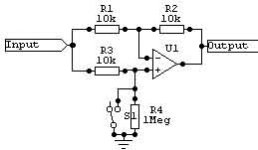
The following circuit is ancient and as useful today as it ever was. With an op amp it is implemented very easily as shown in the diagram below. The resistor values are arbitrary but R1=R2=R3 and R4 must be much higher than R1 , 2 or 3.
The resistor R4 is only used to form a current path for the positive input of the opamp. Reducing its value will decrease the output voltage in non inverting mode from the ideal of 1 to less than that because it acts as a divider with R3.
Assumptions – the opamp has infinite gain , zero output impedance , no input current as the input impedance is infinite. It follows that the differential voltage between + and – inputs is zero. Also assume that R4 is infinite.
An open switch condition:
The input voltage (say V) appears at the + input terminal because there is no voltage drop in R3 as there is no input current . Voltage between the + and – input terminals is zero because of infinite voltage gain. So the – input is also at V volts. Since there is no input current ( in R1 and R3) , there will be no current in R2 and no voltage drop across it. Hence V will also appear at the output. Hence there is no phase inversion. Voltage gain is also unity.
Closed switch condition:
The + input is now at ground potential or zero volts. There is V volts across R3 and the current flows to ground. The – input is also at zero volts ( infinite gain and so Vin+ is = Vin- = 0V). Hence there is a current flow in R1 due to V volts across it. This does not enter the opamp ( zero input current) and hence flows out through R2. Note the current direction. It enters at the – input and flows towards the opamp’s output. Hence the opamps output is more negative than the – input. The current in R1 is V/R1 = the current in R2 . Voltage across R2 is R2x V/R1 = V. Since one end is at zero volts ( - input of the opamp) the output end is at –V as explained above. So we get an inverted unity gain output.
Real world opamps have high input impedance and gain and low Zout as compared to the resistors we are using , so the assumptions we made will hold easily.
Cheers.
Attachments
ashok said:To the moderators:
So is it wrong to put up a new schematic and circuit description?
It's a very useful circuit.
The problem was not one of the circuit being posted, but the posting of someone else's picture expressly against the imbedded copyright notice. It was then compounded by the removal of the copyright notice.
dave
Re: Re: Polarity Inversion circuit
Or more to the point, it wasn't the circuit itself but the particular illustration of it. The circuit itself is not patented (and copyright doesn't cover electronic circuits) and is in the public domain.
se
planet10 said:The problem was not one of the circuit being posted...
Or more to the point, it wasn't the circuit itself but the particular illustration of it. The circuit itself is not patented (and copyright doesn't cover electronic circuits) and is in the public domain.
se
Ashok,
thankyou for writing such a circuit description.
I originally posted this circuit in order that it be of benefit to DIYers who may not have seen it previously.
This selectable polarity line level circuit is very useful for switching audio in-room Absoloute Polarity, and in my experience is required equipment given that the recorded polarity of music cd's is quite random, especially compilation cd's, and also albums where the 'hit' track is often in opposite polarity to the remainder of tracks.
By inverting both the signal into an amplifier and inverting the speaker connections, an amplifier can be compared to the non-inverted throughput condition.
I have found many amplifiers to differ in sonics according to the throughput signal polarity, especially when driven into temporary overload.
Regards, Eric.
I expect that this sonic difference may be due in part to different peak overload behaviours, and speaker/cable back EMF being handled subtly differently.
This circuit would be quite useful for SET amplifiers given their well known +ve half wave/-ve half wave non-linearity.
Another Method
Steve,
watchout, are you sure that the graphic that you posted from a Jensen app note is not copyrighted ?.
I have mentioned the transformer circuit exactly as drawn several times here on the forum, and I agree that it is a fine solution, within the caveats that you advise.
Have you tried this on your systems, and what sonic results have you noted ?.
Regards, Eric.
BUSINESS AS USUAL.
Hi,
Ah, you too.And you know whys these s*ckers do that don't you?
Not sure I understand you here....
Cheers,😉
Hi,
especially compilation cd's, and also albums where the 'hit' track is often in opposite polarity to the remainder of tracks.
Ah, you too.And you know whys these s*ckers do that don't you?
By inverting both the signal into an amplifier and inverting the speaker connections, an amplifier can be compared to the non-inverted throughput condition.
Not sure I understand you here....
Cheers,😉
Idiots In Studios Too
Hi Frank,
In my uderstanding the 'hit track' inversion wrt the rest of the album is likely caused because it has been mixed down in a different studio, or that that it has been 'finalised' in a different facility and hence the opportunity for a polarity inversion.
I have thought about whether this inversion is deliberate or not, and in discussions with other listeners it has been noted that according to (random) overall system polarity, the hit track may sound 'wrong', and the remaining tracks sound correct.
With this knowledge in mind, I hesitate to think that this is deliberate - moreso I think the final mastering guys are not hearing AP.
By this I mean for the same given in room AP for a particular track, by means of flipping the amplifier input polarity and speaker connection polarity together, the amplifier signal throughput polarity behaviour can be compared.
I find that this can make a sometimes substantial differece to the in-room sonics, despite the fact that the in room AP is correct in both cases.
In my view, any polarity inversion control should be at the very souce end (in the cdp), and the speaker connection polarity should be optimised according to the behaviour of the amplifier.
Eric.
Hi Frank,
In my uderstanding the 'hit track' inversion wrt the rest of the album is likely caused because it has been mixed down in a different studio, or that that it has been 'finalised' in a different facility and hence the opportunity for a polarity inversion.
I have thought about whether this inversion is deliberate or not, and in discussions with other listeners it has been noted that according to (random) overall system polarity, the hit track may sound 'wrong', and the remaining tracks sound correct.
With this knowledge in mind, I hesitate to think that this is deliberate - moreso I think the final mastering guys are not hearing AP.
"By inverting both the signal into an amplifier and inverting the speaker connections, an amplifier can be compared to the non-inverted throughput condition."
By this I mean for the same given in room AP for a particular track, by means of flipping the amplifier input polarity and speaker connection polarity together, the amplifier signal throughput polarity behaviour can be compared.
I find that this can make a sometimes substantial differece to the in-room sonics, despite the fact that the in room AP is correct in both cases.
In my view, any polarity inversion control should be at the very souce end (in the cdp), and the speaker connection polarity should be optimised according to the behaviour of the amplifier.
Eric.
RE:Idiots In Studios Too
Hi,
O.K., assuming they do not do it on purpose...after all they have no way of predicting what the absolute polarity is going to be like at Joe Average's place, I vote for the the mere ignorance, other location, studio situation.
Fine, I agree that the polarity inversion should be done at line level, it is more convenient and safer that way.
But once it done there AP is set for the entire chain, i mean a + is a + and a - a - ,right? Inverting at both line linel and amp level simultaneously should not make any difference, should it?
Cheers,😉
Hi,
With this knowledge in mind, I hesitate to think that this is deliberate - moreso I think the final mastering guys are not hearing AP.
O.K., assuming they do not do it on purpose...after all they have no way of predicting what the absolute polarity is going to be like at Joe Average's place, I vote for the the mere ignorance, other location, studio situation.
In my view, any polarity inversion control should be at the very souce end (in the cdp), and the speaker connection polarity should be optimised according to the behaviour of the amplifier.
Fine, I agree that the polarity inversion should be done at line level, it is more convenient and safer that way.
But once it done there AP is set for the entire chain, i mean a + is a + and a - a - ,right? Inverting at both line linel and amp level simultaneously should not make any difference, should it?
Cheers,😉
Double Inversion IOW
Hi Frank,
I mean that the amplifier/speaker connection polarity should be 'set', and then the source output polarity determines in room AP.
I find differences in amplifiers according to the throughput polarity.
SET amplifiers ought to be the most sensitive, and the Pass SE amps somilar.
What I mean is for correct in room AP, there can be differering sonics according to amplifier throughput polarity.
Ime, normal/amplifier/speakers normal can sound different to source inverted/amplifier/speakers inverted.
Eric.
AP.
Hi,
I agree, unfortunately I can't offer much as an exaplanation for this phenomenon...
In theory it should not matter, in practice it does...bummer. 🙄
Cheers,😉
Hi,
Ime, normal/amplifier/speakers normal can sound different to source inverted/amplifier/speakers inverted.
I agree, unfortunately I can't offer much as an exaplanation for this phenomenon...
In theory it should not matter, in practice it does...bummer. 🙄
Cheers,😉
Fine Nuance Differences.
In the case of single ended amplifier circuits this is to be fully expected - in a Pass white paper there is an oscillogram depicting most definate non linearity of upper half wave wrt to lower half wave.
Regarding NFB PP SS amplifiers, yes this should not in theory be an artifact, but in practice I find that it is.
I have some ideas why this is so, but nothing to properly substantiate these subjective findings at this stage.
By subjectively optimising the load polarity wrt the amplifier, I find that the system can be sonically beneficially setup.
Then it remains only to swap the source polarity as required according to programme content.
Eric.
"I agree, unfortunately I can't offer much as an exaplanation for this phenomenon...
In theory it should not matter, in practice it does...bummer. "
In the case of single ended amplifier circuits this is to be fully expected - in a Pass white paper there is an oscillogram depicting most definate non linearity of upper half wave wrt to lower half wave.
Regarding NFB PP SS amplifiers, yes this should not in theory be an artifact, but in practice I find that it is.
I have some ideas why this is so, but nothing to properly substantiate these subjective findings at this stage.
By subjectively optimising the load polarity wrt the amplifier, I find that the system can be sonically beneficially setup.
Then it remains only to swap the source polarity as required according to programme content.
Eric.
Phase reverse circuit:
I used to use this many years ago, but found that the distortion was worse than other methods (analogue switch or relay).
It is elegant though🙂
Phase:
In the world of 2H, where 2 wrongs do make a right, it's clear to see why it matters where the reversal is done.
Absolute phase:
Not so clear here...getting posiitively cloudy in fact😉
I once read a paper which described air as being non-linear. If this is the case, it's the best reason to keep it right - better than the snare drum argument!
Cheers,
dhaen said:I once read a paper which described air as being non-linear.
Jack Dinsdale goes into that in the 1st part of his 3 part Wireless World horn article. His intent there was to show how it affects distortion in the horn's throat.
dave
Dual-polarity amplifier has digital control
I stumbled upon this page tonight Dual-polarity amplifier has digital control and thought that it might be useful for DIYers.
"The circuit in Figure 1 can amplify a signal either in an inverting or a noninverting mode. When switch S1 is on and S2 is off, the circuit behaves as a regular inverting amplifier. When S2 is on and S1 is off, the circuit feeds the signal to the noninverting input of the op amp; thus, the circuit behaves as a noninverting amplifier. If S1 and S2 are monolithic analog switches, you can control this circuit using a digital signal.
I am not sure if the attached images are copyrighted.
Eric.
Attachments

This is a digital pot version of the WW/EW circuit that I referred to previously.
You can implement the same idea using a potentiometer instead of switches (Figure 2). Setting the wiper at the high end of the potentiometer selects inverting-mode operation; setting the potentiometer to the other end selects the noninverting mode. IC1's linear digital potentiometer digitally controls not only the polarity, but also the gain of the amplifier. Because many digital potentiometers come in dual configurations, you can use the second potentiometer for the gain adjustment. "
Cheers.
Attachments
- Status
- Not open for further replies.
- Home
- General Interest
- Everything Else
- Polarity Inversion circuit