Hi all
Brand new here, as a registered member at least. I'm hoping someone may be able to shine a light over my recent trouble with a Rotel RB-970BX.
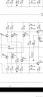
I was working on the amp due to one channel having high DC on its output. The amp employs a differential input stage formed of two opposing LTP's, and is DC coupled from there to the output, including the feedback line back to the LTP's.
So I set about taking my measurements on the faulty channel and found some odd looking voltages (more odd than expected) and realised that this particular point being probed seemed to get the heat sinks warm.... So maybe an RF oscillation or something being introduced with the probe I thought.
For reference moved over to the healthy channel and measured the equivalent node and within 2 seconds the two DC fuses, 4 power trannies and one driver all went open/short. So I am now baffled as I don't see the measurement points as being that sensitive to cause anything beyond a further degree of offset at the output.
I have just checked the input impedance on the old meter I was using (currently travelling) and it is low at 1M, but I'm still not sure if this could be enough to pull the amp that far out of whack.... The failure moment is a bit of a blur but I'm fairly certain the problem point was measuring the voltage on one of the LTP's "tails" with reference to ground (or at least the amplifiers reference point to zero).
If anyone has any thoughts on what may have happened so I don't get a repeat I'd me most grateful as then I can go back to warm cosey tube land!!
Ta for reading!
Dave
Brand new here, as a registered member at least.
I'm hoping someone may be able to shine a light over my recent trouble with a Rotel RB-970BX.I was working on the amp due to one channel having high DC on its output. The amp employs a differential input stage formed of two opposing LTP's, and is DC coupled from there to the output, including the feedback line back to the LTP's.
So I set about taking my measurements on the faulty channel and found some odd looking voltages (more odd than expected) and realised that this particular point being probed seemed to get the heat sinks warm.... So maybe an RF oscillation or something being introduced with the probe I thought.
For reference moved over to the healthy channel and measured the equivalent node and within 2 seconds the two DC fuses, 4 power trannies and one driver all went open/short. So I am now baffled as I don't see the measurement points as being that sensitive to cause anything beyond a further degree of offset at the output.
I have just checked the input impedance on the old meter I was using (currently travelling) and it is low at 1M, but I'm still not sure if this could be enough to pull the amp that far out of whack.... The failure moment is a bit of a blur but I'm fairly certain the problem point was measuring the voltage on one of the LTP's "tails" with reference to ground (or at least the amplifiers reference point to zero).
If anyone has any thoughts on what may have happened so I don't get a repeat I'd me most grateful as then I can go back to warm cosey tube land!!
Ta for reading!
Dave
Attachments
You either shorted something with the probe.
Or if the amplifier is a floating output / bridged topology
you have to use proper methods to scope the output.
since its floating the scope ground can damage the amplifier.
Or if the amplifier is a floating output / bridged topology
you have to use proper methods to scope the output.
since its floating the scope ground can damage the amplifier.
That is a pretty standard input geometry. I've poked around on my Peaveys with both a DVM and a Simpson 266XLPM analog 100000 ohm/volt meter without undue oscillation. I would tend to blame meter probe shorting one thing to another most likely. In any case, amp should be on a light bulb box in the AC feed to limit the size of damage while you probe around. 60 w incandescent bulb up to 500 W, 100 w 500-1000, 1200 w room heater element above that.
Pamona grabbers or Q-balls are safer to probe around with than a 1" long meter probe, IMHO.
Look for Vbe not .6 v, or Vc crammed to one rail or the other, for bad parts. Diodes should have .6 v across them if forwards, and resistors should have a middle drop, not the whole power supply rail drop on one resistor. Capacitors should have different voltages on both ends.
Happy hunting.
Hi guys,
Loving the quick responses! I'll clarify a little further...
The amp is not bridged (I assume you mean balanced bridged?) , although it is floating in regards to earth. The unit becomes grounded through its inputs to the preamp unit as is common. The measurements in question were not the scope but a DMM anywho.
I can't exactly prove it but I can guarantee no shorting and no accidental current setting.
Also, both channels had the same overheating response to the same probing but I assume the out of tolerance channel "failed" to pass enough current through the output stage to cause immediate burn out. The healthy channel on the other hand was just that.... 12mV offset, working fine... Untill I put 1Meg (and a load of wire) between the tail of one of the LTP's and the centre point of the PS ("0V" not grounded).
There's no question in my mind that the meltdown was caused by either Rf oscillation caused by the meter leads or some kind of bias point drift caused by the 1Meg DMM input impedance causing the two halves of the amplifier to fight itself. Of course me having no doubt doesn't mean I'm not wrong.... Doubtless to say....
But I've hit my limit and can't see how to know what happened without either repeating it (costly) or someone having experienced something similar.... Or seeing some reason why that pesky little tail would be so sensitive to RF or loading (being V high impedance node???)
Dave