I received a request for a build thread with TDA7294 point to point.
Please feel free to add comments, questions and suggestions.
DMOS = Lateral Fet = Power MosFET, and are inside these chips.
Here it is step by step, with photos. . .
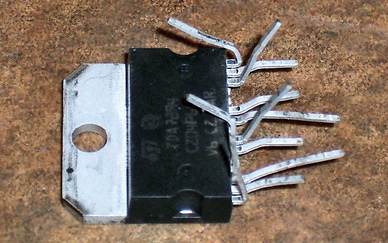
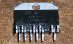
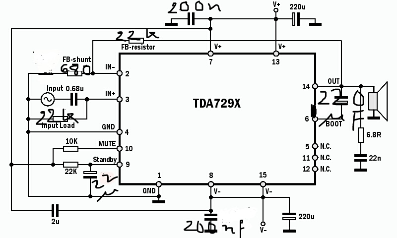
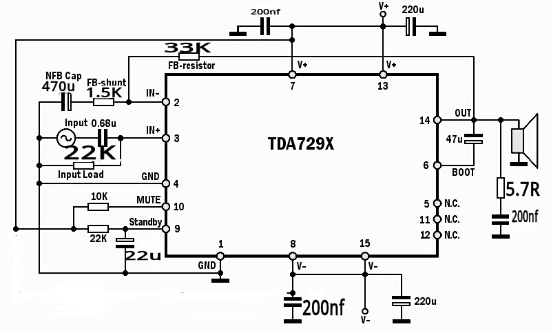
The above photo shows TDA7294/5/6 pinout.
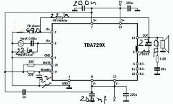
The above photo shows the schematic. It is especially suited to under-volting applications.
Here is a new full power schematic that doesn't require a preamp <click link
Note that TDA7294S and TDA7293 have advanced features at pins 5, 11, and 12. We shouldn't ground those. I've no idea if my TDA7294 chip has those features, so I'm going to remove those pins by wiggling them; with the benefit of more room for soldering.

Now, the pins marked N.C. (5, 11, 12) are definitely not connected, and 12 pins is easier than 15. At this time, I'd like to mention that if you favor parts swapping for fine tuning and quality control, then you may rather use PCB boards for the first build. Here are some compatible kit boards. <--link
The above photo shows: Bending the V+ pins (8, 15) almost to the chip face, bending the V- pins (7, 13) up a bit and then bending the ground pins (1, 4) to midway. This is for rails horizontally across the chip. I've also bent the small signal, down away from the power pins, and spread them very slightly.

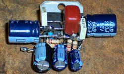
The above photo shows V+ and V- rails with ground at center. I used Gel Flux for assuring good connections done easier.
Those are low-ESR 220u caps. Optionally, you can use parallel pairs of ordinary 100u caps (makes low loss 200u).

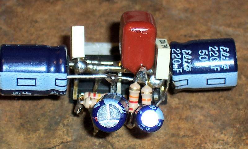
The above photo shows nanofared caps added to V+ and V- for HF bypass duties.
Also shown is 2u polyester at rail to rail (one cap from V+ to V-) for quality control.
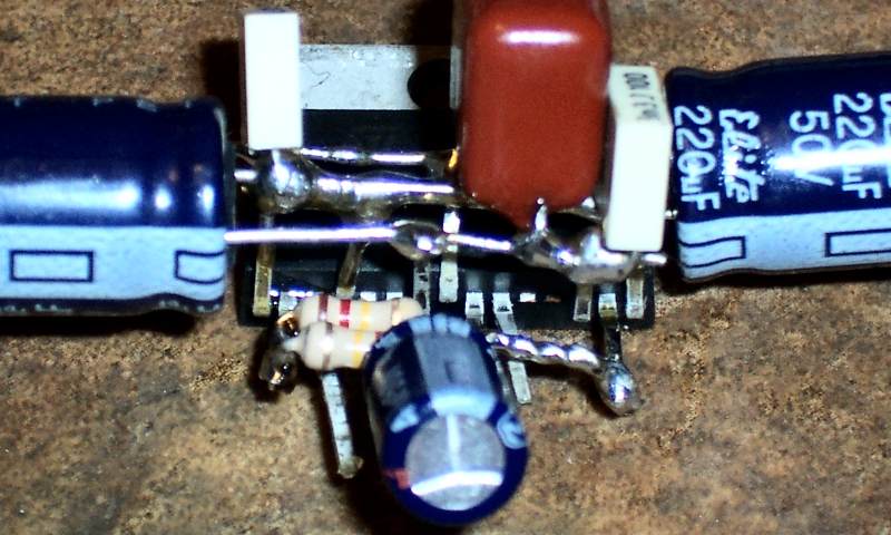
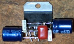
From boostrap pin (6), the 47u boostrap capacitor goes to output pin (14).
The above photo also shows 60k feedback resistor from output pin (14) to inverting input pin (2). That feedback resistor pictured is a parallel pair of 120k, for quality control, and fortunately doubly sturdy with minimized inductance.
Feel free to sleeve anything with heat shrink tubing if you want to (even in that case, please do have some air space in-between).
EASIER BUILD?: If you're going to do any fine tuning or want an easier build, then consider allowing the pins to hang down below the heatsink and put the feedback resistor on back so that you can change values easily and there is much more room to build small signal area. Tone changes by both operating voltage and gain setting, and you will want to fine tune that to your own preferences.
LACKING A PREAMP?: Click Here for alternate higher gain schematic.
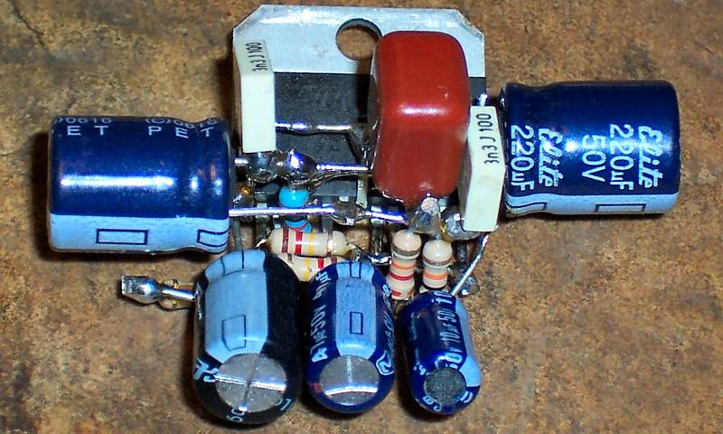
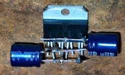
The above photo shows:
Standby (9) to V+ via 22k
Standby (9) to ground via 10u.
Mute (10) to V+ via 10k
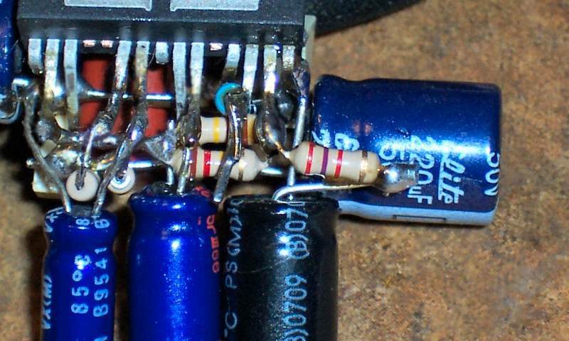
The above photo (bottom side) shows:
220u NFB cap at ground pin (1)
2.7k (carbon) feedback-shunt resistor from NFB cap to to inverting input pin (2)
10k (metal film) input load from ground rail to non-inverting input pin (3)
Notes:
The 220u NFB cap is for authentic chip, but if cull/fake use 100u or smaller NFB cap.
Cable for input and cable for speaker can be added before attaching chip to heatsink.
RF filtering of speaker output RC (6.8R and nanofareds cap) can be added at speaker jack.
RF filtering of input can be added with 1M||220p from + to - at the small signal input cable
Suggested input cap size is 1u (or smaller) and may be at the output of volume pot.
If volume pot is omitted, the input cap size of 1u (or smaller) can be at the RCA jack.
And there it is, TDA729X point to point.
Voltage and current note:
Authentic chips are capable of the specs listed in their datasheets; however, please check ST's Authorized Reseller list to see if you bought or can buy from a reliable source. If you have any reason to suspect that your chip may be either fake or cull or misbehave, please use 4400u (or more) worth of "output cap" (capacitance in series to speaker blocks DC accidents) as a speaker protector, and use 8 ohm speakers. A parallel pair of 2200u creates a low loss 4400u cap suitable for output cap (parallel pair of 3300u creates a low loss 6600u output cap for larger speakers); however, it may be less expensive to purchase authentic chips. Of course mains fuse and speaker jack fuses are good too. Authentic ST chips (from authorized reseller) can drive both 8 ohm and 4 ohm speakers at high power.
First startup:
Use "output cap" to protect your test speaker and use safety bulb test to protect amplifier.
Transformer for TDA729x chips:
TDA7293, 24+24vac toroid or 48vct (24,0,24vac) 5a
TDA7294, 22+22vac toroid or 44vct (22,0,22vac) 5a
TDA7295, 20+20vac toroid or 40vct (20,0,20vac) 4a
TDA7296, 18+18vac toroid or 36vct (18,0,18vac) 3a
Cull/Fake, 15+15vac toroid or 30vct (15,0,15vac) 2a
Power supply:
Please feel free to add comments, questions and suggestions.
DMOS = Lateral Fet = Power MosFET, and are inside these chips.
Here it is step by step, with photos. . .
The above photo shows TDA7294/5/6 pinout.
The above photo shows the schematic. It is especially suited to under-volting applications.
Here is a new full power schematic that doesn't require a preamp <click link
Note that TDA7294S and TDA7293 have advanced features at pins 5, 11, and 12. We shouldn't ground those. I've no idea if my TDA7294 chip has those features, so I'm going to remove those pins by wiggling them; with the benefit of more room for soldering.
Now, the pins marked N.C. (5, 11, 12) are definitely not connected, and 12 pins is easier than 15. At this time, I'd like to mention that if you favor parts swapping for fine tuning and quality control, then you may rather use PCB boards for the first build. Here are some compatible kit boards. <--link
The above photo shows: Bending the V+ pins (8, 15) almost to the chip face, bending the V- pins (7, 13) up a bit and then bending the ground pins (1, 4) to midway. This is for rails horizontally across the chip. I've also bent the small signal, down away from the power pins, and spread them very slightly.
The above photo shows V+ and V- rails with ground at center. I used Gel Flux for assuring good connections done easier.
Those are low-ESR 220u caps. Optionally, you can use parallel pairs of ordinary 100u caps (makes low loss 200u).
The above photo shows nanofared caps added to V+ and V- for HF bypass duties.
Also shown is 2u polyester at rail to rail (one cap from V+ to V-) for quality control.
From boostrap pin (6), the 47u boostrap capacitor goes to output pin (14).
The above photo also shows 60k feedback resistor from output pin (14) to inverting input pin (2). That feedback resistor pictured is a parallel pair of 120k, for quality control, and fortunately doubly sturdy with minimized inductance.
Feel free to sleeve anything with heat shrink tubing if you want to (even in that case, please do have some air space in-between).
EASIER BUILD?: If you're going to do any fine tuning or want an easier build, then consider allowing the pins to hang down below the heatsink and put the feedback resistor on back so that you can change values easily and there is much more room to build small signal area. Tone changes by both operating voltage and gain setting, and you will want to fine tune that to your own preferences.
LACKING A PREAMP?: Click Here for alternate higher gain schematic.
The above photo shows:
Standby (9) to V+ via 22k
Standby (9) to ground via 10u.
Mute (10) to V+ via 10k
The above photo (bottom side) shows:
220u NFB cap at ground pin (1)
2.7k (carbon) feedback-shunt resistor from NFB cap to to inverting input pin (2)
10k (metal film) input load from ground rail to non-inverting input pin (3)
Notes:
The 220u NFB cap is for authentic chip, but if cull/fake use 100u or smaller NFB cap.
Cable for input and cable for speaker can be added before attaching chip to heatsink.
RF filtering of speaker output RC (6.8R and nanofareds cap) can be added at speaker jack.
RF filtering of input can be added with 1M||220p from + to - at the small signal input cable
Suggested input cap size is 1u (or smaller) and may be at the output of volume pot.
If volume pot is omitted, the input cap size of 1u (or smaller) can be at the RCA jack.
And there it is, TDA729X point to point.
Voltage and current note:
Authentic chips are capable of the specs listed in their datasheets; however, please check ST's Authorized Reseller list to see if you bought or can buy from a reliable source. If you have any reason to suspect that your chip may be either fake or cull or misbehave, please use 4400u (or more) worth of "output cap" (capacitance in series to speaker blocks DC accidents) as a speaker protector, and use 8 ohm speakers. A parallel pair of 2200u creates a low loss 4400u cap suitable for output cap (parallel pair of 3300u creates a low loss 6600u output cap for larger speakers); however, it may be less expensive to purchase authentic chips. Of course mains fuse and speaker jack fuses are good too. Authentic ST chips (from authorized reseller) can drive both 8 ohm and 4 ohm speakers at high power.
First startup:
Use "output cap" to protect your test speaker and use safety bulb test to protect amplifier.
Transformer for TDA729x chips:
TDA7293, 24+24vac toroid or 48vct (24,0,24vac) 5a
TDA7294, 22+22vac toroid or 44vct (22,0,22vac) 5a
TDA7295, 20+20vac toroid or 40vct (20,0,20vac) 4a
TDA7296, 18+18vac toroid or 36vct (18,0,18vac) 3a
Cull/Fake, 15+15vac toroid or 30vct (15,0,15vac) 2a
Power supply:
Last edited:

this is lovely, congratulations.
Prehaps this should.. have its own place, where people looking for something verry easy and cool to make. People who are looking for a first build maybe?
Adding a similar "tutorial" on the powersupply part of things, and a basic pre-amp with minimal functions could make this sorthof "ultimate" resource for beginners.
Probably builds documented whitin the same style should be collected, in case if its posted by well known and properly educated members of the forum.
Thank you for the compliment! 😀
In my opinion, 1st build beginners are best served with a solo LM1875 on a board, and a preamplifier unnecessary for it.
However, if one owns 4 ohm speakers, and/or other higher power needs, it may be better to consider the TDA729X or any parallel amplifier for the quality that "current headroom" offers.
I am considering your request for power supply build thread. Since TDA729X's needs are basic, it doesn't need regs and it doesn't need dual mono, but it would like a CRC, yet it needs stiff rails, I could do a "constrained CRC" power supply that will adaptively turn off the CRC feature when higher current is needed for good bass. Do you want a power board with that feature? If not, then there are plentiful basic power supplies already posted online.
My apologies that some weaker sources like onboard computer sound chip, phone, and digiplayer might need a preamp. The TDA729X can do lovely big open sound in high resolution if at standard/low gain; but, the perceived sound-field size shrinks if high gain is used, so I'd rather use a preamp instead of a mid-fi. Click Here to browse the preamplifiers section of diyaudio.com. Upgrade computer sound cards and CD players probably don't need a preamp.
Personally, I would like to have a shunt comp class A buffered preamp made from discrete parts, but run from chip regulators. However, the MooseFet IRF510 preamp from Classic Valve Design will do just fine. Decibel Dungeon also shows a chip preamp biased to class A with two transistors, which is approximately where performance and simplicity meet.
The following attachments are for display at post 1. Previously they were stored on a different server, but it display is more reliable when they are attachments to a thread.
Attachments
-
 pinout.gif13.8 KB · Views: 18,964
 -
 completed.jpg68.7 KB · Views: 12,771
 -
 input.jpg59.4 KB · Views: 11,762
 -
 railbypass.jpg51.4 KB · Views: 12,191
 -
 rails.jpg64.2 KB · Views: 12,223
 -
 mutestandby.jpg50.6 KB · Views: 11,880
 -
 feedbackbootstrap.jpg58.4 KB · Views: 12,001
 -
 pinbend.jpg63.4 KB · Views: 12,270
 -
 pinremove.jpg48.6 KB · Views: 13,032
 -
 schematic.gif12.4 KB · Views: 1,147
Hi Daniel, is the schematic recommended by you.You suggested in the past some 2200 mf near the power supply and some others.Now you have 220uf, and 47 uf in bootstp,60 k in feedback resistor.You also have 2uf between +,_ power supply, you also recommended to short input no 2 to gnd through just 680ohms without caps.is that the latest tweak?
Last edited:
I can't find any 680R on the schematic. This isn't a 47 labs style gainclone. It could be done, but I didn't do it. See the schematic at post 1.. . .you also recommended to short input no 2 to gnd through just 680ohms without caps. . .
Well, really almost any combination that a miller comp discrete amplifier could use, can also be used by the TDA7294. The schematic doesn't necessarily show the latest tweak, but rather it shows a place to start. This page shows low gain, and that puts the component-based audio influence all in one place--the nice clean feedback resistor, not the caps. So, everything is much easier, except that now you need a preamplifier.Now you have 220uf, and 47 uf in bootstp, 60 k in feedback resistor. You also have 2uf between +,_ power supply, . . . is that the latest tweak?
If there was a latest tweak, it would be: Allow the pins to hang down below the heatsink so that there is much more room for building. I built all on one side; however, it would have been much easier to put the feedback resistor and other small signal on the back side.
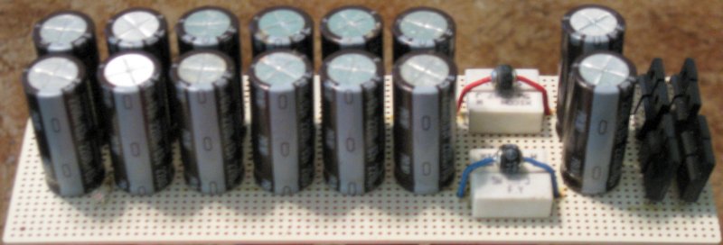
Here are the 2200u caps:Hi Daniel, is the schematic recommended by you. You suggested in the past some 2200 mf near the power supply and some others.
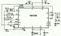
Sorry I mean the shunt resistor ,mine is 680r ,,I just short it to ground,does is it make any difference,,what is the benefit in your case,you are having 220uf +2.2k. From input 3 ,to ground Im using 22k,,also for feedback 22k, yours is 10k and 60k.Power caps near the ic is 220uf +200nf.What is your 2u unpolarised doing there ?The stanby pin 9 is connected with 22uf.I have 220uf as bootstrap,,is it too large?
Last edited:
That looks just like using TDA7294 for a gainclone. I've never tried that. Sorry, I wouldn't know anything about it.
I'm trying again to reply to post #9.
Using the NFB cap helps keep the amp in balance (lets me choose some wild resistor values like whatever sounds good), prevents amplification of DC, makes for more durable amplifier and is part of the audiometric bass tuning. Like any signal cap, the NFB cap can be somewhat time consuming to select, but generally "contest of 5 peers" routine will work rather quickly (for NFB cap and Input cap selection). For treble helper, it is possible to give the NFB cap a little bypass cap (in parallel to the larger cap) with 0.47u or smaller electrolytic and/or 22n or smaller polyester.
Whatever you do with the power circuit, make sure the results are "cooler and clearer" which indicates the chip really liked the change.
Question:
What audio difference is there between 100u vs 220u bootstrap cap?
P.S.
22u standby cap. I like this! You can use 10u~47u range for standby, whereby larger value is larger delay, which avoids turn-on thumps. It also delays turning off, so too large would make for turn-off thumps, but those have less current and thus less significance. Anyway, I like your 22u because it is in the middle of the range and just makes sense.
Omitting the NFB cap omits some dynamics and some safety. 22k input load, 22k feedback, omitted NFB cap, only looks balanced but is actually pretty far off the mark because of the missing cap; and, although, one could find a balance with trimmers, this would vary per each chip if the NFB cap is omitted.Sorry I mean the shunt resistor ,mine is 680r ,,I just short it to ground,does is it make any difference,,what is the benefit in your case,you are having 220uf +2.2k.
Using the NFB cap helps keep the amp in balance (lets me choose some wild resistor values like whatever sounds good), prevents amplification of DC, makes for more durable amplifier and is part of the audiometric bass tuning. Like any signal cap, the NFB cap can be somewhat time consuming to select, but generally "contest of 5 peers" routine will work rather quickly (for NFB cap and Input cap selection). For treble helper, it is possible to give the NFB cap a little bypass cap (in parallel to the larger cap) with 0.47u or smaller electrolytic and/or 22n or smaller polyester.
2u rail to rail? Standard noise filter technique for clearer, less foward, less congested midrange. Its for more fun when playing loud. RCR filter also works.Power caps near the ic is 220uf +200nf.What is your 2u unpolarised doing there?
Whatever you do with the power circuit, make sure the results are "cooler and clearer" which indicates the chip really liked the change.
A 220u bootstrap would be normal for TDA7294S/TDA7293 if run three or four paralleled by the "modular" schematic. I would suggest reducing that to 47u~100u range for the single chip amplifier shown in the schematic.I have 220uf as bootstrap,,is it too large?
Question:
What audio difference is there between 100u vs 220u bootstrap cap?
P.S.
22u standby cap. I like this! You can use 10u~47u range for standby, whereby larger value is larger delay, which avoids turn-on thumps. It also delays turning off, so too large would make for turn-off thumps, but those have less current and thus less significance. Anyway, I like your 22u because it is in the middle of the range and just makes sense.
Last edited:
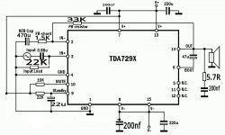
Wow, right on the mark for audiometric feedback-shunt area! Kudos!Plz have a look at this one.It follows your advice....Plz tell me any change in the values for Bass and mid +tweeter sound.
That should have really good bass!
You can change the input cap to 1u if you want to.
Clean bari: You can "double up" the 220u power caps by 220u||220u (makes very clean 440u caps). We wouldn't like the individual power caps larger than 220u; however, we would like the total values to be almost as big as the NFB cap, so a great way to do it is: 220u||220u (parallel pairs).
That's simply an additional 220u on both rails.
Arbitrary bypass may be an error in some cases: Bypass caps, such as the 200n on your power rails should be specifically sized to help the larger caps that they're teamed up with. Need varies per model of cap (and PCB) and can't be predicted by either a schematic or a crystal ball. If the bypass cap size is too large or if they are suddenly much more efficient than the 220u electrolytic, then a ringing peak (bad quality power) results. Polypropylene of 200n would do badly because of efficiency mismatch. However, some wima polyester, ceramic disc, cheap polyester dip cap or fractional value electrolytic, could work okay. The task could be easier if the bypass cap were smaller. Showing a bypass cap on a schematic is gambling, but we could make a safer bet with a smaller cap. The longer the traces between the 220u and bypass cap, the larger the bypass cap. In my photos, the traces are minimal length and so the bypass caps are 3n3 polyester.
Cleaner power for prettier midrange: Try one 2u Or one 3u polyester cap at rail to rail (per the schematic in post 1) and observe to see if you get nicer sounding midrange. This cap can be installed right where the DC cable attaches to the amplifier board. Polyester dip caps, 100v electrolytic and 250v electrolytic are likely candidates to test drive. The actual range is 1u~4u7, so you can "test drive" to find what works for you. RCR can be used, if desired. A smaller size cap could be used if directly attached from pin 13 to pin 15.
Treble: The 470u NFB cap may have less inductance with a smaller body cap, such as a 16v computer grade 470u cap, and that could help. Your amplifier looks quite good on bass; however, the highest treble might be a bit quieter than the midrange. Of course the rail to rail cap should help for quieter&clearer midrange and you should try that first; But, after you've done all you can with clean power, it is time to try some small signal fine tuning.
Try adding a treble bypass cap in parallel to your 470u NFB cap. Little bypass caps suitable for treble clarity boost include 0.47u and smaller electrolytic and/or 22n and smaller polyester. I can't predict what a random model of 470u would like as its partner, so if the schematic showed a treble bypass cap, that would be a non-polar of 4n7 which is too small to conduct audio but it is big enough to dampen/remove inductance of the 470u. Actually, I would leave the bypass cap value blank on the schematic, because, of course, you should experiment to find the perfect size bypass cap for pretty treble.
Your feedback current is far higher than mine, and I've got a 1/2w 60k resistor. You could use a 33k 1/2w comp resistor (high end) or you can make a high end 34K resistor out of a parallel pair of 68K ordinary 1/4w carbon film or metal film resistors. Anyway, there is enough current going though your 33k so that resistor quality matters, and needs to be assured.
Your input load of 22k does less snubbing than my 10k. You snubbed less RF, less HF and less audio. Okay, snubbing less audio was good, but the RF could be a problem. To do a more complete job, add a 330pF (or nearby value) cap in parallel with your 22k input load resistor.
P.S.
I like your design. Starting out with good bass should be quite satisfying.
Last edited:
Thank you Daniel.
I didnt know that feedback resistor should of higher wattage,,last time my 1/4w 22k for tda2040 blew,but i didn't know the reason.
Yes I put a filter at the input.I have a big unpolarized 10u for bass amp and .4u for front speakers.I have been running 5.1 amp with my old configuration.I think my front amp needs a buffer.Becoz i think it is not loud enough .My bass has a buffer+LP filter,my surround amp(tda2040) at the rear has surround circuit+LP filter,,they all sound louder,So I think i will use a buffer+ that two transistor (classA) for my front Amp.
I dont know if introduction of that buffer will make the tda7294 noisy or not.
The greater the resistor current, the worse the resistor quality, so that's why I put a better quality resistor for feedback.
If you want the front channels louder, you'd need either a preamplifier or a higher gain setting. Preamplifier has gain from clean regulated power, so that is a better place to put gain.
If you want the front channels louder, you'd need either a preamplifier or a higher gain setting. Preamplifier has gain from clean regulated power, so that is a better place to put gain.
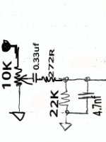
This is my input ,I use 1nf in parallel With 22K for front,and 4.7nf for woofer as Rf filter,I separate SG and PG with 10R.Plz throw some light in this config.
Plz also tell me the value of NFB cap for a mid,tweeter amp configuration.
Plz also tell me the value of NFB cap for a mid,tweeter amp configuration.
Attachments
Last edited:
I don't know what that is, but you might want a buffer in front of it, so that it doesn't apply dampening to other amplifiers run from the same source.
I don't use multi-channel, except for my own TrioPhonic, and the center channel mixer has to have a buffer in front if it, so that piece won't affect the main channels.
I don't use multi-channel, except for my own TrioPhonic, and the center channel mixer has to have a buffer in front if it, so that piece won't affect the main channels.
Unequal equivalent resistances for bias currents on pin2 (IN-) and pin3 (IN+) for
all circuit examples going to cause unnecessary output offset voltage.
all circuit examples going to cause unnecessary output offset voltage.
So far, zero. There's cap in the feedback-shunt, so no DC offset. There's no DC input and it can't amplify DC. It is safety AC coupled for dynamics & durability.Unequal equivalent resistances for bias currents on pin2 (IN-) and pin3 (IN+) for all circuit examples going to cause unnecessary output offset voltage.
This is an ordinary miller comp amp with a normal caveat:
There is a small signal source pushing at the input load resistor
There is a Power Amplifier pushing harder at the feedback resistor
This current is quite different and trumps the voltage settings.
If the resistor values are identical for a pretty schematic, then loud playback comes with dreadful audio quality. An additional problem is that the protection doesn't work when feedback current is too high.
So, I have chosen a different option for cool, loud, durable and clear, shown at post#1. In a 4 year run of this design and similar amplifiers, there has been zero breakage and zero offset.
P.S.
Some amplifiers of this design are like post 1 except for using the option of an 82k feedback resistor and a 22k||220p input load. This can work well with a buffer or a source that has a buffered output.
Last edited:
My 3rd attempt for front speakers.
plz check this one.
plz check this one.
Attachments
Last edited:
- Home
- Amplifiers
- Chip Amps
- Point 2 Point (no PCB) for TDA7293, TDA7294, TDA7295, TDA7296.