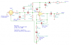
The thread starter was also worried about blowing up inputs. Maybe it's a good idea to increase R8 then; with R8 increased to 220 ohm rather than 47 ohm, the peak current the circuit can push into or draw out of an input will be well below the 100 mA normally used for latch-up testing. This doesn't have to cause signal losses when the order of R8, C8 and R9 is changed a bit.
Attachments
Wow thank you so much MarcelvdG for the schematic! It really helped me a lot!!!
As I saw on the iRak specs sheet, the maximum voltage output is 2Vrms.
How about some zeners parallel to R7 to limit it?
As I saw on the iRak specs sheet, the maximum voltage output is 2Vrms.
How about some zeners parallel to R7 to limit it?
Zeners for low voltages typically have a rather smooth voltage to current characteristic, so they will cause distortion long before they start clipping. I regard that as a disadvantage, some regard it as an advantage (so-called soft clipping). By the way, if you use antiparallel red LEDs rather than antiseries Zeners, you'll have a bit less soft soft clipping and a basic clipping indicator in one (provided the LEDs give enough light at low gain settings and survive the current you get when you shout into the microphone at maximum gain).
Last edited:
Two red LEDs in antiparallel across the output of the circuit of post 21 is probably a better idea (reasonably sensitive LEDs that can handle 20 mA). The current through the LEDs then depends on the output signal level and not on the gain setting, and R8 limits the current. Assuming 1.6 V forward voltage, the maximum RMS output level will be about 1.13 V RMS rather than 2 V RMS, but that's enough to drive a normal line input.
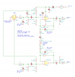
I'm interested in the same circuit, but I would like a balanced output. What changes would ya'll recommend to the schematic to make this with a balanced output?
Something like this maybe? If there is any chance that the output will ever by mistake be connected to an input with phantom supply, then use bipolar electrolytics at the outputs to improve the chances of survival. You can slightly improve the symmetry of the circuit by also using a bipolar electrolytic for the 220 uF capacitor.