I'm pretty sure you have a design issue. The MAX809L has a nominal threshold value of 4V63 and a max under temperature of 4V75. It can draw up to 24 microamps of supply current, although the typical value is less than that. Your circuit is monitoring the difference between +5V and -5V through R428 and R429. The equivalent voltage at the junction of the two resistors is (+5V -(-5V))/2 if the resistors are perfectly matched. The equivalent series resistance to the supply pin of the MAX809L is R428 and R429 in parallel. Using the numbers from your schematic that equivalent resistance is 98K. If the supply voltages are matched (not necessarily a valid assumption) the equivalent voltage should be zero. If there is even 10 microamps of supply current that's almost a 1V drop and the voltage seen across the MAX809L is not sufficient to enable the output to go high. To fix the issue change the values of R428 and R429 to significantly lower values, nominally in the 10K range, and make them different values calculated using the minimum spec'ed value from the +5V regulator and the max value for -5V. Also verify that it works when the tolerances are in the opposite direction.

Hmm… you have an error in layout, cold solder joint, or a bad part somewhere.
Edit: or as pointed out by Jhofland, the threshold settings of the MAX809L supervisor.
Edit: or as pointed out by Jhofland, the threshold settings of the MAX809L supervisor.
@xrk971 I respectfully don't agree. Analyze the subcircuit of R428, R429, and the MAX809L using -5V as reference. The voltage being monitored is 5V - (-5V) through a resistor divider. The voltage Veq = R429 * (Vpos - Vneg)/ (R428 + R429) where +5V and -5V are represented as Vpos and Vneg. You want Veq to exceed the threshold value of the MAX809L somewhat before Vpos and Vneg reach their stable values. For example, I'll choose 9V as that value and a threshold of 4V7. If you go through the math you get that the ratio of R429 to R428 is about 1.09. Separate from that the supply current of the MAX809L goes through the parallel equivalent of R428 and R429 so you need to account for that voltage drop, too.
You're right, I replaced the resistors with 10k, but it didn't help. Then I soldered more 10k resistors on top and the protection started.I'm pretty sure you have a design issue. The MAX809L has a nominal threshold value of 4V63 and a max under temperature of 4V75. It can draw up to 24 microamps of supply current, although the typical value is less than that. Your circuit is monitoring the difference between +5V and -5V through R428 and R429. The equivalent voltage at the junction of the two resistors is (+5V -(-5V))/2 if the resistors are perfectly matched. The equivalent series resistance to the supply pin of the MAX809L is R428 and R429 in parallel. Using the numbers from your schematic that equivalent resistance is 98K. If the supply voltages are matched (not necessarily a valid assumption) the equivalent voltage should be zero. If there is even 10 microamps of supply current that's almost a 1V drop and the voltage seen across the MAX809L is not sufficient to enable the output to go high. To fix the issue change the values of R428 and R429 to significantly lower values, nominally in the 10K range, and make them different values calculated using the minimum spec'ed value from the +5V regulator and the max value for -5V. Also verify that it works when the tolerances are in the opposite direction.
Thank you guys so much!
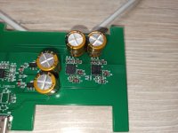
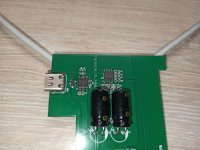
After some use, I got tired of changing the batteries. And I decided to organize the power supply of the amplifier from the household network. Since I didn't want to go beyond the available dimensions, I decided to power the amplifier from charging the phone. In order for the phone charger to output 20 volts, I used the IP2721 PD trigger chip. A virtual grounding circuit was also applied. The voltage has stabilized at +-9.5 volts. With TPS7A3301 and TPS7A4701 chips. I was afraid to use the TPS7A3901 dual stabilizer.

Attachments
annasoh323, xrk971,
Sorry, I haven't had time to measure it yet. When I can measure it, I'll show you.
I think the quality of the current will depend on the phone charger. But this is not accurate.
Sorry, I haven't had time to measure it yet. When I can measure it, I'll show you.
I think the quality of the current will depend on the phone charger. But this is not accurate.
I wasn’t asking for measurements- just sound quality if your ears cannot hear any noise in a headphone amp, that’s generally going to measure well with regards to noise floor.