The PMC TB2+ cabinet
The TB2 cabinet measures 20x30x40 cm (BxDxH) on the outside. Inside it looks like this.

The line that is folded into this cabinet is a straight line with the following dimensions:
A line lenght of 1,145 mtr gives a quarter wavelength resonance frequency of about ~75Hz.
The drawing shows a schematic picture of the line, and shows the damping material distribution.

The red damping layer is a white eggcrate foam 50mm thick. The green small damping piece directly behind the woofer is also an eggcrate white foam, 25mm thick. The port is closed with a foam plug, a piece of reticulated black foam about 3cm thick. The white foam is in perfect condition, the foam in the port opening deteriorates over the years and reduces to dust.
Below some photos. Left the view through the tweeter mounting hole. The top of the first divider is clearly visible. Damping material lines the whole lenght of the line, including the top and bottom of the cabinet. Right is the view from the woofer, with in the center the small piece of 25mm thick eggcrate damping material that basically covers the backside of the woofer.


The view through the removed speaker connector panel. It shows the bottom of the second divider.

The crossover
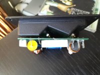
The crossover is mounted on the backside of the connector panel.
The component side. The PCB is doublesided.


The crossover is a simple 12dB/oct lowpass, combined with a 12dB/oct highpass filter. Drivers are connected out of phase.

The 20uF capacitor is an Alcap, 100V, 10% type. The 3,0uF is a Bennic XPP, 5%, 250V type.
Speaker and driver impedance with crossover
This shows the speaker and driver impedance response for both speakers. Red= speaker response, white=tweeter, green= woofer.

Speaker A

Speaker B
From the impedance response the line tuning frequency is about 50Hz. The crossover frequency is around 2,5Khz.
Woofer TS parameters
The woofers are Vifa M17WG-09-08 models. These are old drivers so before I measured the TS parameters I run them through a burn in routine for about 40hrs near maximum excursion (~4mm peak) and frequencies between 20-35Hz. I measured the parameters three times but the differences were small. The method used was "added mass" (15 gramm).


To check on these measurement I looked for data sheets and other measurements. I found more that I expected:
My own measurements are very close to the Peerless specs. The K&T and the Tymphany-Vifa specs are very similar. I don't know what conclusions, if any, can be drawn from these results. For now I will trust my own measurements.
The TB2 cabinet measures 20x30x40 cm (BxDxH) on the outside. Inside it looks like this.
The line that is folded into this cabinet is a straight line with the following dimensions:
- Line lenght 1,145 mtr.
- Line cross section 8x16 = 128 cm²
- Woofer position 17,3cm from the start of the line
- Port cross section 7x15,5cm = 108,5 cm²
A line lenght of 1,145 mtr gives a quarter wavelength resonance frequency of about ~75Hz.
The drawing shows a schematic picture of the line, and shows the damping material distribution.
The red damping layer is a white eggcrate foam 50mm thick. The green small damping piece directly behind the woofer is also an eggcrate white foam, 25mm thick. The port is closed with a foam plug, a piece of reticulated black foam about 3cm thick. The white foam is in perfect condition, the foam in the port opening deteriorates over the years and reduces to dust.
Below some photos. Left the view through the tweeter mounting hole. The top of the first divider is clearly visible. Damping material lines the whole lenght of the line, including the top and bottom of the cabinet. Right is the view from the woofer, with in the center the small piece of 25mm thick eggcrate damping material that basically covers the backside of the woofer.
The view through the removed speaker connector panel. It shows the bottom of the second divider.
The crossover
The crossover is mounted on the backside of the connector panel.
The component side. The PCB is doublesided.
The crossover is a simple 12dB/oct lowpass, combined with a 12dB/oct highpass filter. Drivers are connected out of phase.
The 20uF capacitor is an Alcap, 100V, 10% type. The 3,0uF is a Bennic XPP, 5%, 250V type.
Speaker and driver impedance with crossover
This shows the speaker and driver impedance response for both speakers. Red= speaker response, white=tweeter, green= woofer.
Speaker A
Speaker B
From the impedance response the line tuning frequency is about 50Hz. The crossover frequency is around 2,5Khz.
Woofer TS parameters
The woofers are Vifa M17WG-09-08 models. These are old drivers so before I measured the TS parameters I run them through a burn in routine for about 40hrs near maximum excursion (~4mm peak) and frequencies between 20-35Hz. I measured the parameters three times but the differences were small. The method used was "added mass" (15 gramm).
To check on these measurement I looked for data sheets and other measurements. I found more that I expected:
- A review from Klang & Ton 2/2005
- A Tymphany Vifa datasheet
- Peerless M17WG09-08 data from the loudspeakerdatabase.com
| Data source | Fs | Qms | Qes | Qts | Cms | Rms | Vas | Mms | |
| K&T 2/2005 | 48,68 | 2,36 | 0,67 | 0,52 | 0,89 | 1,69 | 25,69 | 11.97 | |
| Tymphany-Vifa datasheet | 44 | 2,77 | 0,56 | 0,46 | -- | -- | 34 | 11 | |
| Peerless specs | 56,3 | 3,84 | 0.9 | 0,73 | 0,682 | 1,08 | 19,6 | 11.7 | |
| Clio driver A | 59,33 | 3,12 | 0,96 | 0,74 | 0,5997 | 1,43 | 17,13 | 12 | |
| Clio driver B | 57,86 | 3,26 | 0,92 | 0,72 | 0,6163 | 1,37 | 17,6 | 12,28 |
My own measurements are very close to the Peerless specs. The K&T and the Tymphany-Vifa specs are very similar. I don't know what conclusions, if any, can be drawn from these results. For now I will trust my own measurements.
Attachments

Last edited: