Custom driver then. Or some tweaking/balancing of parameters.
Some of their designs have the vent at the end of the line, which I think follows the basic conventions for a TLdesign.
If you look at the cutaways of the floor standers they have a large chamber above the vents, that may help tune and damp things.
Maybe this is the art of Advanced Transmission design, or many hours of experimentation.
Not sure about that.
Mine came out almost exactly the same which was years later confirmed by a member here who just quickly calculated it in hornresp (I think).
Mine came out almost exactly the same which was years later confirmed by a member here who just quickly calculated it in hornresp (I think).
There is no specific "rule" regarding the relationship between Vas and the volume in the TL's line. What is most important to begin with is to determine the optimum tuning frequency for the woofer to be used. That will be affected by the woofer's Qts. If Qts is equal or close to 0.4, the optimum tuning frequency will be equal or close to the woofer's Fs. If Qts is higher than 0.4, the optimum tuning frequency will be lower than Fs, and if Qts is lower than 0.4, the optimum tuning frequency will be higher than Fs. Once you've determined that optimum tuning frequency you can model with different volumes to achieve your desired bass reach and response shape, while keeping an eye on the woofer's excursion (and terminus/port air velocity). Of course you need to use accurate TL-friendly modeling software to get you there.
Paul
Paul
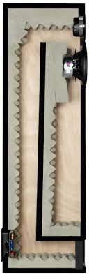
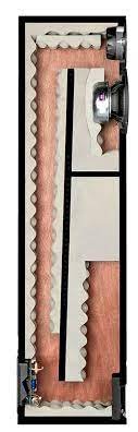
These images show subtle differences in line construction. Obviously different designs for the differing drivers.
Is the bigger volume in No2 away to better match the line?
I am not sure in TL how that additional volume above the mouth is called in TL or maybe horn parlance?
Is the bigger volume in No2 away to better match the line?
I am not sure in TL how that additional volume above the mouth is called in TL or maybe horn parlance?
Attachments
I got hold of bass drivers from "twenty 26" tower speakers : https://pmc-speakers.com/products/archive/archive/twenty26
I was trying to match them with Dayton RS52AN 2" Dome Mid Range and build a speaker. Can someone post the dimensions of cabinet if its available with anyone ?
I was trying to match them with Dayton RS52AN 2" Dome Mid Range and build a speaker. Can someone post the dimensions of cabinet if its available with anyone ?
It's an acoustic low pass filter, so the bigger it is, the lower in frequency for a given gain BW it goes, same as any sealed, vented alignment.Is the bigger volume in No2 away to better match the line?
I am not sure in TL how that additional volume above the mouth is called in TL or maybe horn parlance?
Being a LPF I guess it stops spurious midrange, which is often an issue in ported designs with that nasty rise in port output around 500-1000hz.
Correct in that it sets the horn's HF roll-off, which historically is above the ~250-500 Hz baffle step in a wide range system and above the ~100-160 Hz 'boom - punch' BW for live sound apps.Being a LPF I guess it stops spurious midrange, which is often an issue in ported designs with that nasty rise in port output around 500-1000hz.
- Home
- Loudspeakers
- Multi-Way
- PMC bass driver T/s parameters?