Yes but it would be a different amplifier, with a conventional BJT output. Simple devices change and smaller bias voltage would not work.Could this amp be adapted to work with bjt output?
And what about the vbe bias?
The class A (another thread) has excellent low distortion, but it is impractical because of the radiated heat and very low efficiency. The 2004 error correction version would have a bit lower distortion than the amp of this thread (PM-AB2), however it has one major drawback - the unique error correction used in PM-AB1 acts also like an output stage current/voltage limiter, and the maximum output swing falls dramatically with low load impedance. It is fine to 4ohm, but not so fine to 2ohm or 1ohm, which says that if there are dips on speaker impedance curve the amp may start clip (both in current and voltage) and it does not sound good, in fact it sounds awful. I found it when I made a bridged version of PM-AB1, which was clipping with lower impedance at high power. This is the main reason why I suggested this simpler version, PM-AB2, which does not suffer from output clipping with low impedance load. Similar, but not so much pronounced issue was also with the class A low distortion amp. Again, the sensing transistors of the correction circuit limited the output current, though not so early.And how does this compare to your other pieces namely the class A version and the 2004 300ma bias version?
Regarding sonic test, I am quite sure that you, me or nobody else would tell a difference in a level matched double blind test. All 3 amps do not suffer from high order harmonic distortion and their distortion profile is below both audibility limits and speaker distortion.

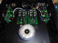
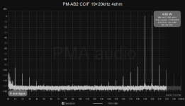
Hello friends, the PCB's from China have arrived, they are assembled and the complete 2-channel amplifier was made, as you can see at the picture attached. It has worked immediately, just setting the idle current by a trim pot (you know I prefer to work hard rather than to debate too much 😉). This is ideal behaviour for the beginners. Below please see some basic measurements, the operation is decent. 30W/4ohm. You can see THD and THD+N vs. power at 1kHz and 5kHz / 4ohm, THD and THD+N vs. frequency at 16W/4ohm, and CCIF IMD.
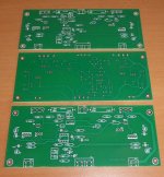
The board photos are attached as well. The boards are larger than necessary, but I have pre-drilled heatsinks in my proto case so I make it to fit. And it is easy to assembly and measure.
I have some spare PCBs and could sell 2 pcs, if anyone would be interested.

The board photos are attached as well. The boards are larger than necessary, but I have pre-drilled heatsinks in my proto case so I make it to fit. And it is easy to assembly and measure.
I have some spare PCBs and could sell 2 pcs, if anyone would be interested.
Attachments


I like the design in the OP the most. Simple and effective.
This thread is overlooked. Get -8dB lower THD easily with just 2 extra resistors.
With the local NFB.

Without the local NFB, by breaking the line near 2 0.22 resistors.

Note: the bias is about 200ma in both cases.
CFP with mosfet can reach similar result, but CFP cannot be bootstrapped. In contrast, you can bootstrap common source. The output voltage swing would be heavily limited with CFP.
This thread is overlooked. Get -8dB lower THD easily with just 2 extra resistors.
With the local NFB.
Without the local NFB, by breaking the line near 2 0.22 resistors.
Note: the bias is about 200ma in both cases.
CFP with mosfet can reach similar result, but CFP cannot be bootstrapped. In contrast, you can bootstrap common source. The output voltage swing would be heavily limited with CFP.
Last edited:
Actually, you don't need the local feedback resistors. Just use the capacitors.
Here is the THD without the opamp. The high performance unit buffer is here.

Here is the THD without the opamp. The high performance unit buffer is here.
No. LAT Fets only need 0.5~1 Vgs to bias. Using the circuit in #26, the bias would be too high.Can I adapt above schematic for LAT Fets?
Do have Q1 and Q4 voltage gain?
No. There will be no voltage gain. There is strong negative feedback that the output voltage will strictly follow the input voltage.
Thanks, just looking for a voltage gainstage(3x) to drive lat fets at +/-50V with standard +/-15v opamp.
R4, R5 and R6 to be re-calculated (reduced) for lower Vgs of lateral MOSFETs.Can I adapt above schematic for LAT Fets?
P.S.: I tried some simulations and distortion is higher with laterals.
Last edited:
Thanks,In another thread I try to get about 100W with 10n20/10p20 fets with massive opamp error correction.
Just need a non inverting gainstage(3x)between the opamp and lat fets stage.
https://www.diyaudio.com/community/threads/help-with-lat-fet-schematic.424463/
Just need a non inverting gainstage(3x)between the opamp and lat fets stage.
https://www.diyaudio.com/community/threads/help-with-lat-fet-schematic.424463/
As per post #1 changes: R1 = R2 = 470R, R4 = R6 = 3k3, R5 = 22k, ECX10N20, ECX10P20. It should work.
Thanks again, I will be using +/- 36v…45v power supply. Go for 400mA bias with the lat fets.
I like your schematic just wondering if using other transistor can lower distorsion?
I also have lme49710(to99) and opa1611 on adapter.
I like your schematic just wondering if using other transistor can lower distorsion?
I also have lme49710(to99) and opa1611 on adapter.
Distortion with laterals will be higher than with hexfets due to their low transconductance and high Rdson.
I have a lot of lat fets I like to use.
And lineup has already nice distorsion figures with his lat fet designs.
But only low power,
And lineup has already nice distorsion figures with his lat fet designs.
But only low power,
- Home
- Amplifiers
- Solid State
- PM-AB2 MOSFET amplifier with error correction and low distortion