Hello all, years ago I posted at DIYaudio a thread about my MOSFET amplifier with an error correction (it was called PM-AB1), see
https://pmacura.cz/pm_ab1.html
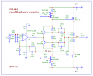
The amp was working well and dozens were built by DIYers, without any major issues.This is another attempt with a different circuit solution of error correction. Basically it is a mosfet output stage with error correction that is placed inside feedback loop of the opamp. The circuit is simple and it shows very good simulated parameters. The circuit shown is a basic one and it would be provided with voltage regulators for opamp rails and possibly input coupling cap to block DC failure from input signal. I think I may build a sample and look how the real circuit would work.
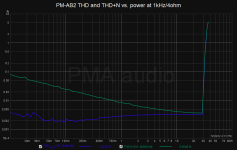
Attached is a basic schematic, THD vs. power simulations at 1kHz/4ohm and 10kHz/4ohm and a simulation file, this time in MicroCap11, which I prefer to LTSpice, mainly because of the abilities to plot THD and THD+N vs. level plots and also because of the models used. So here we go.
P.S.: idle current of the output stage is 80mA, considerable reduction compared to PM-AB1, so it is not any "room heater".
================
1st sample built 05/20/2022 and measurement are and will be added
https://pmacura.cz/pm_ab1.html
The amp was working well and dozens were built by DIYers, without any major issues.This is another attempt with a different circuit solution of error correction. Basically it is a mosfet output stage with error correction that is placed inside feedback loop of the opamp. The circuit is simple and it shows very good simulated parameters. The circuit shown is a basic one and it would be provided with voltage regulators for opamp rails and possibly input coupling cap to block DC failure from input signal. I think I may build a sample and look how the real circuit would work.
Attached is a basic schematic, THD vs. power simulations at 1kHz/4ohm and 10kHz/4ohm and a simulation file, this time in MicroCap11, which I prefer to LTSpice, mainly because of the abilities to plot THD and THD+N vs. level plots and also because of the models used. So here we go.
P.S.: idle current of the output stage is 80mA, considerable reduction compared to PM-AB1, so it is not any "room heater".
================
1st sample built 05/20/2022 and measurement are and will be added
Attachments
-
 PM-AB2_413_118_simplsch.png20.8 KB · Views: 1,684
 -
 PM-AB2_distsim1k.png8.6 KB · Views: 1,537
 -
 PM-AB2_distsim10k.png8.9 KB · Views: 838
 -
PM-AB2_413_218.ZIP9.4 KB · Views: 270
-
pm-ab2.asc5.2 KB · Views: 229
-
 PM-AB2_thdnpower_4R_1k.png19.2 KB · Views: 619
 -
 PM-AB2_thdnfreq_4R_10W.png17.4 KB · Views: 1,334
Last edited:

Could you perhaps sim it with opa551 552? These are high v opamps that could share the rails with the output with simple crc filter and simplify this circuit even further
Could you perhaps sim it with opa551 552? These are high v opamps that could share the rails with the output with simple crc filter and simplify this circuit even further
No problem (to simulate). The result with 551 is much much worse, especially at higher frequencies. I would recommend LT1122 with rails +/-22V. I have tested dozens of these opamps and they have much lower distortion than the datasheet indicates. The other option is OPA445 with up to +/-45V rails, but again, distortion will go higher. I will test the amplifier soon with LT1122, OPA627, OPA134 and OPA445. As this amp is similar to former PM-AB1
https://pmacura.cz/pm_ab1.html
I expect the results to be very good, probably better than the older model.
How many digits worse are we talking here? Ive actually begun to use 552 for my 3886 composite project, rails +/-28v. The highs arent as smooth as my older one using ne5532 on lm317 reg but not so much so that its a deal breaker.
My thought was that the noise added by the simple regulator is counter productive to the quality of whatever the opamp that ends up connected. I could definitely hear what was being done to the regulator when i used ne5532, opa1656 in my previous circuit.
Id like to ask you if theres a flaw in the architecture of these high voltage opamps that makes them perform worse.
Not trying to be contradictive here. Just wanna learn and make better amps. 🙂
Attachments
Last edited by a moderator:
Oh man i just had an idea... so simple i had to mentally smack myself.
One could custom wind 0-13-22 0-13-22 trafo and dedicate 0 13 0 13 to the opamp. Seperate lower noise rectifier, no ic reg, and audio grade opamps can be used. 👍
One could custom wind 0-13-22 0-13-22 trafo and dedicate 0 13 0 13 to the opamp. Seperate lower noise rectifier, no ic reg, and audio grade opamps can be used. 👍
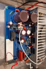
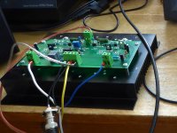
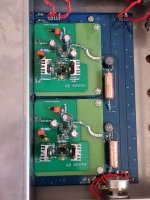
The sample is built, and good news, is working properly! Some photos below. As it is similar to PM-AB1, I used the old PCB from that amp and make some small changes to it.
Attachments

How many digits worse are we talking here? I
20dB and more worse with OPA551. It is up to you, it will work. You will get worse PSRR without voltage regulators, and in any case you will not be able to utilize the whole rail swing, because of Vgs of Mosfets. However, it is up to you. To me, LT1122 with 2x22V rails is the choice. You know, I am a difficult guy to be advised 🙂, and in any case I ask everything documented by measurements. EE is my profession.
20db is a lot...
I will have to follow your advice. I spent the whole day trying to tame the metalic treble of the opa552 circuit and its just not happening. It sure is dynamic tho, but its not high end.
At 22v theres also ne5534 for the budget conscious. 🙂
Btw my circuit is an lm3886 composite. Am i using the full rail swing with the 552?
But then a pair of lightly loaded ic regs are its own set of problems... i think ill keep at this passive psu solution. 551 isnt exactly sota but its also not gomna be the limiting factor in such designs as yours and mine
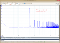
Okay, here is the 1st measurement on the real thing. Opamp is OPA134, load 4ohm, 25W/4ohm. It could have been better but it is acceptable. Idle current is 100mA and BTW even after running 30 minutes at 6W/4ohm 1kHz sine it has not changed. There is not much capacitance in the PSU filter bank, so we can see 100Hz and multiples from the PSU ripple PSR, hopefully below any audibility threshold. Hopefully no significant 50Hz and multiples, which would indicate to (PCB) wiring loop issue.
More measurements will be needed, with changed idle current as well.


More measurements will be needed, with changed idle current as well.
Last edited:

Could you perhaps sim it with opa551
No problem (to simulate). The result with 551 is much much worse, especially at higher frequencies. I would recommend LT1122 with rails +/-22V. I have tested dozens of these opamps and they have much lower distortion than the datasheet indicates. The other option is OPA445 with up to +/-45V rails, but again, distortion will go higher. I
How many digits worse are we talking here?
20dB and more worse with OPA551.
20db is a lot...
I will have to follow your advice.
Well, I have measured this amplifier sample with OPA445. As a result, it is not that bad. We have about twice more noise with OPA445(expected) and some distortion rise (not as much as per simulation). So it is usable and you could feed this opamp from full rails.
Again, as many time, it has shown that simulation is not everything, just only a first step when building an amplifier. So it is definitely not enough to sit in the armchair and play with PC. Yes it is easier 😉. Post #1 for a reference of THD/frequency distortion with OPA134.
Attachments
Thanks for that experiment. Its definitely not night and day. And without the regulators there'll be layout advantages to boot.
However the opa445 is too expensive, almost 4 times the price of 551. And ive already made up my mind to add in the regs in my next board spin.
Will report back in couple weeks how it sounds compared to no regs.
However the opa445 is too expensive, almost 4 times the price of 551. And ive already made up my mind to add in the regs in my next board spin.
Will report back in couple weeks how it sounds compared to no regs.
Thanks for the info, @donovas .
I have checked the amplifier with OPA627, OPA134, LT1122 and OPA445. Parameters with the first three mentioned are almost same, differing mainly in noise only. Distortions are almost identical. The noise is as the named order of opamps, from lowest to highest. Noise and distortion is highest with OPA445. LT1122 might be a happy medium, as with +/-22V allowed rails it is able to give 50W/4ohm.
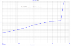
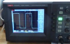
I have also made some scope and HF measurements. Square response is good (see also post #7), the amp accepts capacitive load.
In audio band, the behaviour is nice. Visible traces of MOSFET crossover distortion start at 50kHz, see the attached scope time plot and also the distortion spectrum, still THD is below 1%. But we do not have 50kHz large level signals in music recordings.
This amp should be very easy to build even for the beginners. It does not show traces of hidden issues. The only setting element is pot R17 (10k), see post #12. This must be a multi-turn trim pot, I use Spectrol 64Y 10k. The pot sets idle current measured as a voltage drop across R14 (or R15), set 10mV.
I have checked the amplifier with OPA627, OPA134, LT1122 and OPA445. Parameters with the first three mentioned are almost same, differing mainly in noise only. Distortions are almost identical. The noise is as the named order of opamps, from lowest to highest. Noise and distortion is highest with OPA445. LT1122 might be a happy medium, as with +/-22V allowed rails it is able to give 50W/4ohm.
I have also made some scope and HF measurements. Square response is good (see also post #7), the amp accepts capacitive load.
In audio band, the behaviour is nice. Visible traces of MOSFET crossover distortion start at 50kHz, see the attached scope time plot and also the distortion spectrum, still THD is below 1%. But we do not have 50kHz large level signals in music recordings.
This amp should be very easy to build even for the beginners. It does not show traces of hidden issues. The only setting element is pot R17 (10k), see post #12. This must be a multi-turn trim pot, I use Spectrol 64Y 10k. The pot sets idle current measured as a voltage drop across R14 (or R15), set 10mV.
Attachments

Several remarks on construction and setup
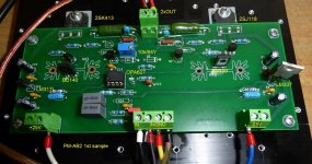
The output device I have used are Hitachi 2SK413 and 2SJ118. The reason is that I have some stock of these genuine parts. Genuine Hitachi parts look like this (click to enlarge)

Before buying anything on e-bay, I strongly recommend to check, because the internet is full of fakes.
Parts like IRFP240/9240 should be usable as well, it would be necessary to set different voltage between Gates of Q5 and Q6 by R17 trimpot to get 10mV across R14.
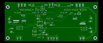
The photo of the 1st assembled sample is attached below. Please note that it was built on another PCB (PM-AB1) and some modifications of the PCB had to be made. Please also note the big LM337 TO-220 part, as I did not have LM337L in my stock.
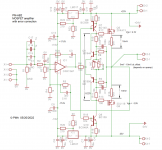
Attached is also the real sample schematics with important voltages shown. The only setup device is R17 to trim 10mV across 0R1 resistors.
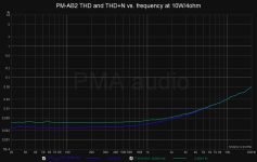
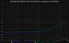
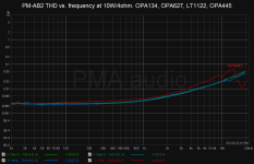
The last image is THD vs. frequency measurement at 10W/4ohm with 4 different opamps, OPA134, OPA627, LT1122, OPA445. It shows that 3 of them measure almost identical, only OPA445 differs.
The output device I have used are Hitachi 2SK413 and 2SJ118. The reason is that I have some stock of these genuine parts. Genuine Hitachi parts look like this (click to enlarge)
Before buying anything on e-bay, I strongly recommend to check, because the internet is full of fakes.
Parts like IRFP240/9240 should be usable as well, it would be necessary to set different voltage between Gates of Q5 and Q6 by R17 trimpot to get 10mV across R14.
The photo of the 1st assembled sample is attached below. Please note that it was built on another PCB (PM-AB1) and some modifications of the PCB had to be made. Please also note the big LM337 TO-220 part, as I did not have LM337L in my stock.
Attached is also the real sample schematics with important voltages shown. The only setup device is R17 to trim 10mV across 0R1 resistors.
The last image is THD vs. frequency measurement at 10W/4ohm with 4 different opamps, OPA134, OPA627, LT1122, OPA445. It shows that 3 of them measure almost identical, only OPA445 differs.
Attachments
PMA, how about opa1641 in your circuit against the others? I just got done trying it out in my composite preamp design (simple diamond buffer global feedback x3 gain) and could not believe what i was hearing. Its truly SOTA. Miles ahead of other opamps ive listened in this circuit.
Might be the key to elevating a simple design like yours to a world class level
Might be the key to elevating a simple design like yours to a world class level
Attachments
PMA, how about opa1641 in your circuit against the others?
Based on parameters
OPA1641 will be usable in PM-AB2. It has low noise and low distortion in low and mid frequencies. Basically, all JFET unity gain stable opamps will work here with similar results. The distortion is given mainly by the output stage and opamp loopgain. Only opamps with poorer distortion profile like OPA445 or OPA551 will make worse overall result.
Re your claims on "sound quality", I am not that enthusiastic, under controlled test conditions (with expectation bias and excitement bias excluded) all the good JFET opamps do sound almost same.
In case you are interested, OPA1641 was included in one of my opamp tests in 2013, see the results attached.
Attachments
Could this amp be adapted to work with bjt output?
And what about the vbe bias?
And how does this compare to your other pieces namely the class A version and the 2004 300ma bias version?
I planned on further developing my 3886 composite amp until learning today that there's a chip shortage 😭. So i just might join building your amp and also do my own layout (with your blessings ofcourse). Will share the files here if thats what happens.
Would like to set myself as the guinea pig for bjt output version with 2sc5200/1943 pair
Also may i make a suggestion to tweak the output values for +/-28v supply? 22 0 22 0 trafos are whats most commonly available around me and after the double bridge rectification its 28v
- Home
- Amplifiers
- Solid State
- PM-AB2 MOSFET amplifier with error correction and low distortion