Hey-Hey!!!,
I just spoke with Mikey of Magnequest about, among other things, the Dynaco A441. Seems he will be willing to charge "about" $300 each for his modern production copy. He has the original Dynaco prints, so I suspect it will be just as they were wound before. Only, now there is optional lamination materials and such as that to offer improvements, grain oriented M4 comes to mind...
If enough folks line up with a fist full of green, I think he'll make a run ov them.
Turns out the Acro TO-350 is nearly the same as far as the windings go, 15% tertiary winding. Core is another story.
regards,
Douglas
For those still interested in, this is what I found on
http://www.jadis-electronics.com/pages_eng/info/index_info.htm
”JADIS amplifiers offer for the first time in the world an original linkage of tubes with the output transformer. This transformer has been designed to function with a distributed triple load : the anode, the cathode and the screen have separate windings, while the output tubes function practically as though they work in a triode mode. “
I don’t think this way of doing is patented anyhow.
Still wondering how they squeeze out 40 W in pure class-A from 2 x EL34 as Jadis claims.
😎
Hi,
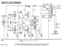
And they won't for the first circuit, to the best of my knowledge, to use that kind of topology was the QUAD II.
Impossible IMHO...The JA 30 used a pair of KT88s in class A and barely reached 30W.
Cheers,😉
I don’t think this way of doing is patented anyhow.
And they won't for the first circuit, to the best of my knowledge, to use that kind of topology was the QUAD II.
Still wondering how they squeeze out 40 W in pure class-A from 2 x EL34 as Jadis claims.
Impossible IMHO...The JA 30 used a pair of KT88s in class A and barely reached 30W.
Cheers,😉
Attachments
Hey-HEy!!!,
On power out of the A441/TO-350 OPT, with its 15% tertiary winding when used for cathode feedback and hook up the power tubes as pentode is about equal to the B+ supply squared divided by the anode load. The anode dissipation rating sets the max B+ for the class A operation, and with the anode winding impedance, sets the available power. I get 35W from a pair of KT90. which is about 3x the power I put into the driver stage.
THe individual grids need about 80 vrms to get into the beginning of grid current and don't quite ever cut off. So for more power, bigger anodes, with higher B+ and lower a-a impedance. WIth only two power valves, it gets very difficult to get more than 50 Watts unless you want to get really heavy into NFB to bring the output z into line.
regards,
Douglas
Frank, it was more or less a rhetorical question about the power 😉
Douglas, it can be estimated somewhat simpler: A pure class-A has a theoretical efficiency limit of 50%. An EL34 has a limit of 25 W anode dissipation and 8 W of G2 dissipation. If you can make full advantage of G2 for output power (which you can’t with UL) it makes 33W max. idling power. With 2x EL34 you can maximally have 50% of 2 x 33W = 33W output. Take into account some 5% losses in the OT and you can’t have the full B+ for signal amplitude, it will be substantial lower.
For a PP, the signals of the output tubes sum together. The non-linear (“quadratic”) behaviour of the tubes cancels out then. That way you can have around 50% efficiency for a class-A. But it is still impossible to get out a clean 40W from 2x EL34 in class-A. And that is what they claim for the "Orchestra". But never mind, the Orchestra is a good sounding amp to my experience.
Cheers
Hi,
Ever listened to a JA-30 with Tungsol 6550s?
In which case Mrs.Y would have the Orchestra in the room given a decent speaker...
Cheers,😉
And that is what they claim for the "Orchestra". But never mind, the Orchestra is a good sounding amp to my experience.
Ever listened to a JA-30 with Tungsol 6550s?
In which case Mrs.Y would have the Orchestra in the room given a decent speaker...
Cheers,😉
- Status
- Not open for further replies.
- Home
- Amplifiers
- Tubes / Valves
- Plytron/Amplimo 4070-CFB OTF's