Hi,
The output stage uses MJ15024/25 devices. the transformer has a sticker specifying 500VA, 52 volt output. I measured 73v filtered with about 18mv noise. the capacitors are elna 27000uF 80v (I've built a 50watt, single ended amp that has 188000 uF per 35v rail, now that will generate sparks!). I don't have an LCR meter that measures that high, but after nearly 30 years they could be ready for replacement. I'll test them with a load later.
The output stage uses MJ15024/25 devices. the transformer has a sticker specifying 500VA, 52 volt output. I measured 73v filtered with about 18mv noise. the capacitors are elna 27000uF 80v (I've built a 50watt, single ended amp that has 188000 uF per 35v rail, now that will generate sparks!). I don't have an LCR meter that measures that high, but after nearly 30 years they could be ready for replacement. I'll test them with a load later.
Nice big transistors. 250V, 16A. Havent seen those pupy's before. When I forst got my Plinius. One of the channels had a problem. My advice is to chect all other components (semis and resistors) as it is probably DC coupled. I found some leaky transistors in mine . Also emiter resistors worth checking/replaceing before replacement of the o/p transistors (expensive).
Bringing this thread back from the dead!
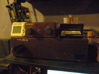
I just saved a Plinius II, III and IV combo from the scrap pile.
A quick look in the poweramp suggests it needs a rebuild.
The preamp psu uses the same mj15003/15004 used as the poweramp outputs.
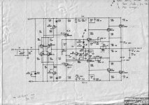
Thanks for the schematic, Butcher.
I just saved a Plinius II, III and IV combo from the scrap pile.
A quick look in the poweramp suggests it needs a rebuild.
The preamp psu uses the same mj15003/15004 used as the poweramp outputs.
Thanks for the schematic, Butcher.
Bringing this thread back from the dead!
I just saved a Plinius II, III and IV combo from the scrap pile.
A quick look in the poweramp suggests it needs a rebuild.
The preamp psu uses the same mj15003/15004 used as the poweramp outputs.
Thanks for the schematic, Butcher.
Really from a scrap pile similar like this ??
https://www.ameslab.gov/files/imagepicker/k/kgibson/Scrap-metal-heap-copy.jpg
This is really amazing.
The use of bjt power output devices for discrete serial regulators is really nothing special. But if there is in use parallel regulators for the pre amp section, then it would be no ordinary.
Schematics would be interesting in any case.
Um, It would help if the email address is functional! "mcseatmore@gmail.com"
Anyhow mate, look back i this thread as I have already posted it!
Tony.
Anyhow mate, look back i this thread as I have already posted it!
Tony.
Hi Tony
If it wouldn't be too much trouble I would also very much like a copy of the Plinius II schematic.
jonathanrapley1@hotmail.com
Thanks
If it wouldn't be too much trouble I would also very much like a copy of the Plinius II schematic.
jonathanrapley1@hotmail.com
Thanks
Has anybody already tried to play with such Triple CFP? Any simulation to show how to make it without oscillation? My first attempts are already bad at simulation level with common modern BJT...
It would be very intersting to be able to use this topology as the bias is very stable as mainly dictated by pre-driver vbe.
Any recommandation?
What is the goal of R35 R36?
It would be very intersting to be able to use this topology as the bias is very stable as mainly dictated by pre-driver vbe.
Any recommandation?
What is the goal of R35 R36?
Attachments
Last edited:
Those Emitter resistors are there to prevent VHF (RF) oscillation by lowering HFE (gain) It is common practice with RF amplifiers. It is a way of equalization. I cant name the correct terminology but I tink I know a tin or tew!!
IT IS A PRODUCTION METHOT OF MATCHING THE DC COUPLED DRIVER TRANSISTORS 😉
Tony.
Thanks for the educated reply !
ps ROCK ON!
IT IS A PRODUCTION METHOT OF MATCHING THE DC COUPLED DRIVER TRANSISTORS 😉
Tony.
Thanks for the educated reply !
ps ROCK ON!
Should they be on the emitter side, I would agree and not ask.Those Emitter resistors are there to prevent VHF (RF) oscillation by lowering HFE (gain) It is common practice with RF amplifiers. It is a way of equalization. I cant name the correct terminology but I tink I know a tin or tew!!
But as they are on the collector side, appart from adding some miller effect , I don't get it...
What is the goal of R35 R36?
DC coupled amplifier. I am not sure what those resistors on the collectors are for. Same function as R37, R38 I bet.
Might be another way of offering a better match of the transistor pairs.
Let us know if one discovers there function !
Thanks Macleod
Tony.
triple CFP with gain is possibly even more difficult to stabilise than the triple CFP.
see Roender's triple for a good design that works.
see Quad/Crimson for a triple quasi that works.
see Roender's triple for a good design that works.
see Quad/Crimson for a triple quasi that works.
- Home
- Amplifiers
- Solid State
- Plinius III 80 watt p/c class AB Amplifier