Hi,
I was thinking about the knob…I like the idea of an amp having only two knobs, one marked as “Volume” and the other one as “Tone”. While we may have seen such a thing, now the “tone” control got a different character…
Just thinking….may it be that different positions of the knob will suit to a particular type of music? For example, I was experimenting with an Aleph current source on my ZEN V3. I installed a switch to disconnect the 1.5 K resistor, making it a CCS (switch off). I noticed that I preferred a constant current source while listening to easy music, or Jazz, while with Rock I preferred the Aleph current source (switch on). I even had an idea to connect a 1K ohm pot in series with 820 ohm resistor, so the range would be from 820-1820 Ohm, which should give me various percentage of AC gain….
By the way, I tried a 1.8 K resistor instead of 1.5 k. Did not like the sound. Returned to 1.5 K. Or none (switch off)...

Regards,
Vix
I was thinking about the knob…I like the idea of an amp having only two knobs, one marked as “Volume” and the other one as “Tone”. While we may have seen such a thing, now the “tone” control got a different character…
Just thinking….may it be that different positions of the knob will suit to a particular type of music? For example, I was experimenting with an Aleph current source on my ZEN V3. I installed a switch to disconnect the 1.5 K resistor, making it a CCS (switch off). I noticed that I preferred a constant current source while listening to easy music, or Jazz, while with Rock I preferred the Aleph current source (switch on). I even had an idea to connect a 1K ohm pot in series with 820 ohm resistor, so the range would be from 820-1820 Ohm, which should give me various percentage of AC gain….
By the way, I tried a 1.8 K resistor instead of 1.5 k. Did not like the sound. Returned to 1.5 K. Or none (switch off)...
Regards,
Vix
Question regarding PLH
Could there be a little mistake in the text under fig 8?
Should this not read:
Figure 8 shows .... through R1 and R2. The source of Q1 follows
the Gate input signal and drives Q2 in Common Source
mode (v..
And as a result
would read:
The Drain of Q1 delivers an inverted and amplified version of the
input signal to drive transistor Q3 in Common Drain mode
(cur...
Or am I missing something obvious?
Regards
Could there be a little mistake in the text under fig 8?
Figure 8 shows .... through R1 and R2. The source of Q1 follows
the Gate inout signal and drives Q3 in Common Source mode (v..
Should this not read:
Figure 8 shows .... through R1 and R2. The source of Q1 follows
the Gate input signal and drives Q2 in Common Source
mode (v..
And as a result
The Drain of Q1 delivers an inverted and amplified version of the
input signal to drive transistor Q2 in Common Drain mode (cur...
would read:
The Drain of Q1 delivers an inverted and amplified version of the
input signal to drive transistor Q3 in Common Drain mode
(cur...
Or am I missing something obvious?
Regards
Greg Erskine said:I was just about to download the datasheet for the IRF244 and found it is now obsolete. I guess it may be still available for now.
It will work with just about any part. IRFP240's are a clean
replacement.
lumanauw said:With this quality of "homework", you should be able to make commercial product from it (another FirstWatt maybe?), but you decided to put it as DIY project?
It might make a product, but I don't have to decide at this
moment, and it doesn't hurt me to put it out there in the
meantime.
😎
Vix said:On page 7 I read “ P1, R6 and C4 form a filter to take out power supply noise..." On the schematic (Fig. 8) it is C5?
Shall we dare to think what's gonna be next?
Right you are, and also the reference to P1 and R3 which should
be P3. Both are fixed, and Desmond is putting it up on
www.passdiy.com and it's also being sent to AudioXpress.
😎
Re: Question regarding PLH
Thanks. Missed that one too.
😎
rtirion said:Could there be a little mistake in the text under fig 8?
would read:
The Drain of Q1 delivers an inverted and amplified version of the
input signal to drive transistor Q3 in Common Drain mode
(cur...
Thanks. Missed that one too.
😎
Nelson Pass said:
It will work with just about any part. IRFP240's are a clean
replacement.
Yippee! Sounds like I can use my IRFP044's...
Dennis
It might make a product, but I don't have to decide at this moment, and it doesn't hurt me to put it out there in the
meantime.
Right 😀 I forget to include a factor that a Nelson Pass have reached such an enlightment level, that his true customers will still buy authentic product, even the original schematic is floating around and they can built/buy the clone. The original gears have somekind of invincible thing that those who owns them is satisfied perfectly 😀
lumanauw said:his true customers will still buy authentic product, even the original schematic is floating around and they can built/buy the clone.
maybe Nelson has done studies on his customers but who is a typical Pass customer?
I doubt DIYers account for a meaningful portion of his customer base.
Typical customer . . . ?
I think that anyone could be his true customer. It's largely possible. 🙂
Regards
jH
I think that anyone could be his true customer. It's largely possible. 🙂
Regards
jH
Magura, Circlomanen and Nelson Pass
Thanks for the heads up on the MOSFET alternatives.
I have IRFP450, IRFPG40 and IRFPG50 at hand and it looks like the IRFP450 may be just OK.
Thanks for the heads up on the MOSFET alternatives.
I have IRFP450, IRFPG40 and IRFPG50 at hand and it looks like the IRFP450 may be just OK.
Xed Version ?
I wonder whether an Xed version is still possible with 2 stages ?
I have had an X-ed, 3-stage, JLH using MOSFETS (IRF610s and IRFP044s), with a less elegant way of biasing the 2nd stage, and it sounds great. Split rails, no coupling caps.
Couldn't think of how to do it in 2 stages ..........
😕
Patrick
Hi, JH,
I've worked on the first question on my homework 😀
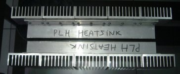
I cut the heatsink, so it will be mounted vertically. From my experience, the same heatsink if placed vertically does more effective heat sinking than if it is placed horisontally.
All the pieces are bolted together to thick L extrusion, with many bolts (my hands are tired bolting all of them tightly 😀)
Between L extrusion and heatsink pieces, I put white heatsink compound, so the heat transfer from L extrusion to the heatsink will be maximal. The transistors will be mounted on the L extrusion.
I've worked on the first question on my homework 😀
I cut the heatsink, so it will be mounted vertically. From my experience, the same heatsink if placed vertically does more effective heat sinking than if it is placed horisontally.
All the pieces are bolted together to thick L extrusion, with many bolts (my hands are tired bolting all of them tightly 😀)
Between L extrusion and heatsink pieces, I put white heatsink compound, so the heat transfer from L extrusion to the heatsink will be maximal. The transistors will be mounted on the L extrusion.
Attachments
This was how I did it first, nothing to write home about :
http://www.diyaudio.com/forums/showthread.php?postid=507045#post507045
This is how it is today (see attachment).
Please give me some specific ideas how to get rid of the JFET and combine the phase splitter into the long tail pair.
Patrick
(PS I think I understand the AX circuit pretty well.)
http://www.diyaudio.com/forums/showthread.php?postid=507045#post507045
This is how it is today (see attachment).
Please give me some specific ideas how to get rid of the JFET and combine the phase splitter into the long tail pair.
Patrick
(PS I think I understand the AX circuit pretty well.)
Attachments
Hi Lumanauw,
Looks very good.
Ya . . . okay, you finish your homework first. Then, do my homework for me. But, make mine horizontal. Otherwise, he will find out. 😀
O . . . yeah . . . and, if you make PCB, leave one for me.
Regards
jH
Looks very good.
Ya . . . okay, you finish your homework first. Then, do my homework for me. But, make mine horizontal. Otherwise, he will find out. 😀
O . . . yeah . . . and, if you make PCB, leave one for me.
Regards
jH
Hi, JH,
Since this is "THE" homework, I planned not to use any PCB at all 😀. They will add parasitic track capacitance, confusing signal accepted by each component. I also planning to isolate the whole transformer (a second casing, maybe?)
I will make it wire-to-wire connection between component legs, trying something like JonathanCarr (Lyra) saying about "air dielectric". He used to monitor very small vibration (making phono pick up) and monitoring very high frequency disturbance (Mhz region), and he uses this technique. I must try it 😀
Hi Lumanauw,
Ya . . . good decision.
Don't want to see this thread being covered by PCB group buying. 😀
Ya . . . my F1 is also of p2p.
Ya . . . carr is a good vibration source. 😱
Ya . . . you will hear MHz music. 😀
All the best!
I will watch. The teacher will watch.
Regards
jH
Ya . . . good decision.
Don't want to see this thread being covered by PCB group buying. 😀
Ya . . . my F1 is also of p2p.
Ya . . . carr is a good vibration source. 😱
Ya . . . you will hear MHz music. 😀
All the best!
I will watch. The teacher will watch.
Regards
jH
jh6you said:Don't want to see this thread being covered by PCB group buying. 😀
ok
/Kari
- Status
- Not open for further replies.
- Home
- Amplifiers
- Pass Labs
- Plh