I have to chose from two PSU schematics for a 6c33 set amp
One is "old school" but it requires alot of diffrent voltages and the other one uses just 180V.
Tommorow i have to place the order for the power transformer so please vote 🙂.
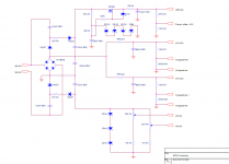
One is "old school" but it requires alot of diffrent voltages and the other one uses just 180V.
Tommorow i have to place the order for the power transformer so please vote 🙂.
Attachments
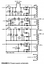
Hi,For less headaches it would make sense to go for the 180V schematic.
That being said a tube rectifier circuit would be sonically better.
That being said a tube rectifier circuit would be sonically better.
in schematic to the right, the two bias voltages interact with each other! Also, zeners are noisy.
zeners can be bypassed. There is a lot to be said for the lower cost of the single winding and the mosfet regulator can't hurt either. Since the bias circuit is a voltage only (well in practicality) I don't see any issue with running them both from the one supply - prepared to be corrected though
The bias voltage in the second schematic is not concerning me. I can change that part. But i'm worried about the overall performance of the circuit compared to a more classical design like the one on the left. But using a single winding is....cheap.
If you do use the schematic to the right, I recomend you add a cap from each of the bias pot wipers to ground. It will filter out zener noise and also help ensure that that drivers load doesn't vary with bias setting of the output stage.
Agreed. In fact, that's pretty much how all fixed bias amps (that aren't mono-blocks) are. He may have a slight AC interaction between the two as-is, but if he adds the caps to the wipers it should be diminished.
Since the bias circuit is a voltage only (well in practicality) I don't see any issue with running them both from the one supply
Agreed. In fact, that's pretty much how all fixed bias amps (that aren't mono-blocks) are. He may have a slight AC interaction between the two as-is, but if he adds the caps to the wipers it should be diminished.
Last edited:
The one on the left.
I prefer the independent diode bridges.
Me too..
Due to the use of a voltage doubler, you'll have a harder time controlling voltage ripple in the supply on the right. With a voltage doubler you get 2x the ripple at half the frequency compared with "straight" rectification as in the schematic on the left.
I do like the simplicity of the schematic on the right, though. And with the zener regulators, any ripple should be heavily attenuated. Put a decent cap - say 10 uF - across the zener stack for the bias supply, though. The B+ zener stack is already filtered.
~Tom
I do like the simplicity of the schematic on the right, though. And with the zener regulators, any ripple should be heavily attenuated. Put a decent cap - say 10 uF - across the zener stack for the bias supply, though. The B+ zener stack is already filtered.
~Tom
For the schematic on the right, the caps coming off the 180V xfmr depend on equal + and - currents thru them to avoid building up a permanent charge voltage. The load does not look particularly symmetrical versus AC polarity. You might want to simulate this with estimated loading to see what happens.
- Status
- Not open for further replies.
- Home
- Amplifiers
- Tubes / Valves
- Please vote for one of the schematics.