Hello,
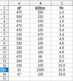
I am trying to decide on a reasonable number for the corner frequency for the RC of the output tubes(KT88/KT120) PP. I found numbers in the range from 1 to 33.9 Hz - see attachment.
I know the resistor value is basically set by the datasheet. Please tell me a reasonable number for the f3dB frequency.
Edit: there will be no global negative feedback
Attachments
Last edited:
If you are going to use global negative feedback, or even shorter loop negative feedback that includes that RC coupling inside the feedback loop, you have to consider the phase shift of the RC network.
The total gain and phase of everything inside the loop, must not go positive phase when there is still gain.
Otherwise, you will have motor-boating.
The total gain and phase of everything inside the loop, must not go positive phase when there is still gain.
Otherwise, you will have motor-boating.
My 2 most recent push pull amplifiers use Ultra Linear, and solid state current sink in the cathode coupled phase splitter.
There are no other negative feedback paths than that in those amplifiers (all local negative feedback loops).
Makes life simple.
Note:
The output stage is DC current balanced to less than 100uA (does not cause early output transformer saturation).
Very well matched high transconductance tubes, and self bias makes it possible to just plug-and-play.
That makes all the difference for bass at 20Hz.
Last edited:
I agree about Ultra Linear all the quality audio transformer companies in the UK supplied them for use in their top end power amps,its a pity they are now nearly all defunct.
When I built my KT88 with UL output, I used these across 600R
PEG124PL347VQL1 KEMET | Mouser Canada which are 470uF 100V 22000 hours @ 105c so they will last for the life of the amp in theory.
PEG124PL347VQL1 KEMET | Mouser Canada which are 470uF 100V 22000 hours @ 105c so they will last for the life of the amp in theory.
Answering the OP question: up to a point it´s a matter of personal choice: some want the input capacitor to be so large as to be ""invisible" within the Audio band, those would choose, say, 1 Hz.
Others (me included), want it to do something "useful", which would be limiting very low frequencies, (inaudible to begin with) which the output transformer would not pass, or very poorly, and which to boot the speaker would not reproduce either.
So I very much like your pre-choice of 16Hz.
Can´t go wrong with it.
Last edited:
Answering the OP question: up to a point it´s a matter of personal choice: some want the input capacitor to be so large as to be ""invisible" within the Audio band, those would choose, say, 1 Hz.
Others (me included), want it to do something "useful", which would be limiting very low frequencies, (inaudible to begin with) which the output transformer would not pass, or very poorly, and which to boot the speaker would not reproduce either.
So I very much like your pre-choice of 16Hz.
Can´t go wrong with it.
Thank you ! 16 Hz was not an intentional choice, I was more in the 5-7 Hz range, to have no phase shift from 50-70Hz upwards. I do not really understand the need for 1 Hz when the OPT turns off at 20 Hz ?
I'm not going to pretend superior knowledge here, (so this also becomes a question for our much more expert commenters!) but isn't the “F” in
Or maybe I'm getting it mixed up with dBV volts decibes versus dBP power decibels. That old
Help!
⋅-=≡ GoatGuy ✓ ≡=-⋅
Z = 1/(2πFC) … which rearranges to
F = 1/(2πZC)
in Hz, but also specifically the 'corner' where the passed signal is ½, or –6 dB attenuated from the source side? I know there is some phase shift, and that the imaginary-plane product might only be 0.707 attenuation 'cuz of that. But I just don't remember whether it is ½ or 1/√2;F = 1/(2πZC)
Or maybe I'm getting it mixed up with dBV volts decibes versus dBP power decibels. That old
dBV = 20log10(Vo/Vi) versus
dBP = 10log10(Po/Pi)
... thing.dBP = 10log10(Po/Pi)
Help!
⋅-=≡ GoatGuy ✓ ≡=-⋅
It's 1/√2 in terms of amplitude, 1/2 in terms of power and -3dBBut I just don't remember whether it is ½ or 1/√2
Last edited:
Suppose an amplifier has just these 3 low frequency poles:
An input RC coupling of -1 dB at 20Hz, the driver to output stage RC coupling is -1 dB at 20 Hz, and the output transformer is - 1dB at 20 Hz.
The total is -3 dB at 20 Hz, and - 9 dB at 10 Hz.
But if you will be using global negative feedback, you probably do not want to have these 3 low frequency poles all at the same frequency.
> Suppose an amplifier has just these 3 low frequency poles:
Three same poles with "negative" feedback makes an oscillator. Each pole makes 45 degrees phase shift at the corner, 90 degrees at infinity, so at "some" in-between point you have 60+60+60= 180 degrees total phase shift. Which makes "negative" really +positive+.
If you WANT an oscillator, you have to also consider Gain. If you do not want an oscillator, and ignore the shifts, Murphy's Law *ensures* the gain will be "right" for an oscillator.
There's many feet of shelf for books discussing this issue. But then there is the very ill-defined response of an iron-core and the many things we call "loads".
Plagiarize plagiarize plagiarize!!! Smarter folks than you have fought this dragon and found suitable combinations.
Special case: if you will routinely OVER-load the amp, you may want to shorten the power tube coupling. In guitar amps, even above 82Hz. This means faster recovery, or less "fainting" after a hard slam.
And without negative feedback, you will not get an oscillator even though the 3 poles line up.
(unless you do not pay attention to ground loops, wire placement, interstage to output transformer coupling, and many other things).
Design an amplifier, and get an oscillator.
Design an oscillator, and get an amplifier.
It has happened more often than most people think.
(unless you do not pay attention to ground loops, wire placement, interstage to output transformer coupling, and many other things).
Design an amplifier, and get an oscillator.
Design an oscillator, and get an amplifier.
It has happened more often than most people think.
- Home
- Amplifiers
- Tubes / Valves
- Please tell me a reasonable number for the RC of a KT88 PP output stage.