Chris
The graphs will make a little more sense if you use the dB-Voltage probe since this will then give you a clearer plot of gain v frequency.
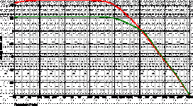
I assume you have performed an ac analysis of the closed loop performance of the JLH with the standard theoretical gain, (Ra+Rb)/Rb, set to 13 (2k7) and 910 (200k).
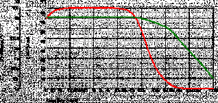
SIMetrix uses a default value of 1V for the input of an ac analysis. Your first graph shows an output from the amp of 13V within the pass-band, falling at higher frequencies as the transistor gain drops. This matches the calculated gain and is correct.
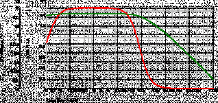
Your second graph shows an output voltage of around 250V (it should be a little higher but I suspect you did not re-adjust the output dc offset when you altered the feedback resistor value). This indicates a simulated gain of 250 which does not match up with the theoretical gain. The reason for this is that the standard gain equation assumes an amplifier with an infinite open-loop gain, whereas the JLH has a relatively modest open-loop gain of around 1400 (depending on the transistors used).
The error when using the standard equation is not significant when calculating 'normal' gains but the gain with your 200k feedback resistor is far from normal and would not be encountered in a practical power amp.
Geoff
The graphs will make a little more sense if you use the dB-Voltage probe since this will then give you a clearer plot of gain v frequency.
I assume you have performed an ac analysis of the closed loop performance of the JLH with the standard theoretical gain, (Ra+Rb)/Rb, set to 13 (2k7) and 910 (200k).
SIMetrix uses a default value of 1V for the input of an ac analysis. Your first graph shows an output from the amp of 13V within the pass-band, falling at higher frequencies as the transistor gain drops. This matches the calculated gain and is correct.
Your second graph shows an output voltage of around 250V (it should be a little higher but I suspect you did not re-adjust the output dc offset when you altered the feedback resistor value). This indicates a simulated gain of 250 which does not match up with the theoretical gain. The reason for this is that the standard gain equation assumes an amplifier with an infinite open-loop gain, whereas the JLH has a relatively modest open-loop gain of around 1400 (depending on the transistors used).
The error when using the standard equation is not significant when calculating 'normal' gains but the gain with your 200k feedback resistor is far from normal and would not be encountered in a practical power amp.
Geoff
Thanks Geoff,
What I want to do is to play with different values of R7 first before I make the actual change to the amp. Right now the amp is sounding very detail and true to each individual CD, I just want to add just a tiny little bit of distortion to the sound, anyway here is the current schematic of the amps that I am listening to; I will play around with the sim/ and try to understand different analysis results;
Regards,
Chris
Attachments
correction
Sorry guys,
the last post was the testing 200k feedback value; here is the correct one
Sorry guys,
the last post was the testing 200k feedback value; here is the correct one

- Status
- Not open for further replies.
- Home
- General Interest
- Everything Else
- Please teach me how to read graph