bjornagain said:
It seems to work equally fine in simulation with even or uneven gain, no big differencies. But I wonder how it sounds?
the reason is that the output stage is really two SE stages working in tandem (180 degree out of phase). So it doesn't matter if they have equal or unequal gains.
The same goes with "unmatched" output devices in this particular design.
As to your sound question: in simulation and in reality, the BJT version appears to be slower, and less symmetry in driving capacitive loads. the mosfet version on the other hand does not blink when driving capacitive and low-impedance load.
I have always thought about running something similar to your design B to see if it can get rid of the nasty turn-on inrush current problem in my mosfet jlh1969. never had the time to do it tho.
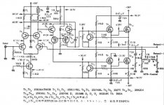
Real schema for design A #1
There is some nice features:
- bias temp comp with D1 and Th
- dual positive supply +50 V and +36 V
- cascaded fet's in va-stages
- output mos fet 2SK831 driven by source follower 2SK214
- current limiting
- negative output impedance (makes it possibly to motion feedback of a speakercone and alter Qts of the driver).
Attachments
Hi Bjornagain,
The first schematic is new to me but I think the feedback arangement is to make it more positive, not negeative... Rod Elliot has some good pages on that topic, with a similar feedback idea to adjust the output impedance..
I will probbably be a fine amp, but simplicity has been thrown out of the window.. Most, if not all, nice features of the first amp can easely be incorperated in the second schematic as well.. I cann't make up my mind anymore... I tend to like simplicity, and all that cascoding, multiple Vrails .. hmmm ...
goodluck,
Thijs
Current or voltage....
Hi
The feedback arangement in the first schematic is allways negatif...the pot is for variation of output impedance.
The amp can work as a voltage amp or as a transconductance (current output) amplifier.
When the weper of the pot go to the left side we have a voltage amp...when it go to the right we have a tranconductance amp.
The small 0,22 Ohms resistor at the output is for sensing the output current in the transconductance mode! 😉
tschrama said:Hi Bjornagain,
The first schematic is new to me but I think the feedback arangement is to make it more positive, not negeative... Rod Elliot has some good pages on that topic, with a similar feedback idea to adjust the output impedance..
Hi
The feedback arangement in the first schematic is allways negatif...the pot is for variation of output impedance.
The amp can work as a voltage amp or as a transconductance (current output) amplifier.
When the weper of the pot go to the left side we have a voltage amp...when it go to the right we have a tranconductance amp.
The small 0,22 Ohms resistor at the output is for sensing the output current in the transconductance mode! 😉
Hi,
I was offcourse reffering to the output impedance (becoming more positive instead of negative as Bjornagain writes), I was not refering to the feedback itself being positive.. w're building amplifiers here, not oscilators ......sorry for the confusion..🙂
I was offcourse reffering to the output impedance (becoming more positive instead of negative as Bjornagain writes), I was not refering to the feedback itself being positive.. w're building amplifiers here, not oscilators ......sorry for the confusion..🙂
tschrama said:Hi,
I was offcourse reffering to the output impedance (becoming more positive instead of negative as Bjornagain writes), I was not refering to the feedback itself being positive.. w're building amplifiers here, not oscilators ......sorry for the confusion..🙂
I got it!! 😉
Sorry to! 🙂
Hi! Friends,
Design A looked fimiliar. One of my friends had made one on similar topology, based on an Elektor design.
I remember it as a very well behaved design with very rich and lively sound.
Check out the schematics:
http://www.geocities.com/pa_schematics/240Wpoweramp.html
I have not as yet come across a thread discussing this particular amp.
Regards
Rahul
- Status
- Not open for further replies.
- Home
- Amplifiers
- Solid State
- Please rate designs for n-ch mosfet amp