I'll have to wait until next week to see if what kind of OPamps my supplier has on stock. I'll definitely try with a slower one.
I'll try adding base resistors to Tr4 and Tr5 as well.
One thing that I was thinking of...
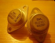
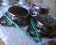
I'm just poking around in the dark here.... but All of the N fets (BUZ 901) that I ordered were counterfeit (they weren't even functional) luckily the supplier replaced them with original ones.
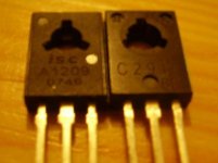
Since my driver transistors Tr5 and Tr4 are from the same supplier, there's a possibility that one or both could be counterfeit as well although they do seem to work. (I'm not sure how the originals should look, my understanding is that they are currently only manufactured by Sanyo, and these don't look like Sanyo transistors)
I have attached a pic of the driver pair.
Thanks.
I'll try adding base resistors to Tr4 and Tr5 as well.
One thing that I was thinking of...
I'm just poking around in the dark here.... but All of the N fets (BUZ 901) that I ordered were counterfeit (they weren't even functional) luckily the supplier replaced them with original ones.
Since my driver transistors Tr5 and Tr4 are from the same supplier, there's a possibility that one or both could be counterfeit as well although they do seem to work. (I'm not sure how the originals should look, my understanding is that they are currently only manufactured by Sanyo, and these don't look like Sanyo transistors)
I have attached a pic of the driver pair.
Thanks.
Attachments
Mooly said:Don't know if I've missed something on the way. PCB layout. You have had to wire the FETs to this I take it. Short wires ? The gate stopper needs to be on the FET itself.
Couldn't get the link at the start to open.
Yes, I wired the mosfets, but the wires are less then 4cm long (!1.6")
Originally the gate stopper was on the board but I've removed it and now it's directly soldered to the mosfet gate. (the protection zenner are not connected now, but this is a prototype anyway and the BUZ mosfets should have a protection diode built in.
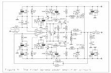
In case someone can't access the link at the top with the schematic, I've attached it.
Attachments
Hi Tibi,
Got the link to work. There's nothing obviously amiss on the circuit. You really need a 'scope to see whats happening.
When you start mentioning counterfeit and non functional parts parts anythings possible.
Got the link to work. There's nothing obviously amiss on the circuit. You really need a 'scope to see whats happening.
When you start mentioning counterfeit and non functional parts parts anythings possible.
Still can't see anything obvious. Just watch the grounding. You could I think looking at the PCB connect it so that the zobel and speaker return possibly affects the stability. The zobel return and speaker return should go back to the star ground.
Layout is so important.
good luck with it, will look in tomorrow
Layout is so important.
good luck with it, will look in tomorrow
Yep, your tr4 and 5 maybe a problem. The one on the left is second source equivalent from isc, have tried to use them, not even close to the real sanyo. The one on the right seems to be cheap chinese copy, which is even worse. I think you could get better results using bd139 140 if not fake than those.
Could you put up a pic of the mosfets and the opamp. Damm so now even the buz series is being copied, Im starting to wonder about that opamp too, maybe they just renumbered some junk. Above the number there must be a BB marking on. Seems your supplier is like the ones in my country, only supply fakes.
Where is Mures, country?? Ill check with a friend if he still has some of those sanyos left and can spare. I bought 1000 pcs each last year direct from sanyo, they were kind enough to match them to complementary pairs for me too, but I sold them as I have changed to other transistors.
homemodder said:Yep, your tr4 and 5 maybe a problem. The one on the left is second source equivalent from isc, have tried to use them, not even close to the real sanyo. The one on the right seems to be cheap chinese copy, which is even worse. I think you could get better results using bd139 140 if not fake than those.
Could you put up a pic of the mosfets and the opamp. Damm so now even the buz series is being copied, Im starting to wonder about that opamp too, maybe they just renumbered some junk. Above the number there must be a BB marking on. Seems your supplier is like the ones in my country, only supply fakes.
Where is Mures, country?? Ill check with a friend if he still has some of those sanyos left and can spare. I bought 1000 pcs each last year direct from sanyo, they were kind enough to match them to complementary pairs for me too, but I sold them as I have changed to other transistors.
Arrgh! Well at least I can blame the problems on those drivers rather then my mistakes 🙂
I'm from Romania actually, Mures is a province in Transylvania (I'll have to update my location) It would be awesome if your friend still has any originals left, the problem is that even if I order new ones from my supplier, chances are I'll get the same crappy ones.
In case you friend still has a few left, let me know please, I'd be glad to pay the full price for them and cover the mailing expenses.
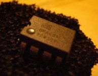
I'm going post the pics of the mosfets that I'm currently using (I believe those to be original), The fake mosfets that I had replaced, and the OPamp.
Thanks!
Mooly said:Still can't see anything obvious. Just watch the grounding. You could I think looking at the PCB connect it so that the zobel and speaker return possibly affects the stability. The zobel return and speaker return should go back to the star ground.
Layout is so important.
good luck with it, will look in tomorrow
Hi Mooly, thanks for the tips.
Yeah, originally I was going to use the use the the ground on the PCB as the speaker return, but I've realized that it's not the best idea, so it's connected to the star ground. I'll try returning the zobel to the star ground as well.
This always work for me when using opamps, try putting 0.1uf film or ceramic decoupling cap from pin 4 to ground and from pin 8 to ground on IC1, opamps are known to oscillate without these for stabilization caps. Best wishes
The opamp's "BB" logo doesn't look right to me... I only have some OPA2134's here but it still doesnt look right :x
If you have trouble getting 2SA1209/2SC2911, and you can get Fairchild transistors, try KSA1381/KSC3503 from them. They are very close to the Sanyo's.
BTW, I tried this design in LTSPICE a while ago, and I couldn't get it to work stable in there either. I concluded that the voltage gain in the output stage was too much hassle, and abandoned it.
Hi Jaycee,
My BurrBrowns don't look like that either. The design shouldn't be that critical on transistor types, if it is that's poor design in my book. Untill I joined DIY I never realised the problem of fake parts was so big. Always buy from recognised sources though.
Decoupling the IC. -- A small cap directly soldered to the supply pins is best which is 4 and 7 in this case.
some true
TRUE NO1
often many of us..... me also rush into constructing pcb after see a schematic we think is nice .....VERY WRONG !!!! since our brain is busy withis wonderfull and new schematic the pcb we make has a lot of mistakes
TRUE NO 2
very often forum members especially in issues like that start with change this and change ...improove this and improove that !!!! The suggestions might be very correct or may be not so correct and also the side effects of any change in nfb cap or vas cap and so on canot be calculated versus use or abuse of your amp
( who are we to play god on somebody elses schematic ????)
of course forum memebrs do this out of good will and effort to help ....but sorry thats not really enough
TRUE NO3
your approach is kind of wrong in my opinion .....cause if you change capacitor bla sugested by user bla bla then may oscilation stops at this point but then there is a million of other things that needed to be checked for side effects ..... which will have the result that replacing of cap bla ....sugested by user bla bla ... will make the amp stop oscilating on bench and when you put your amp on the "road" some kid will touch the treble button or the volume button or the bass buton and at the slightest sign of overdrive you are going to loose a pair of nice speakers .
A simple approach
Forget the pcb for a minute ...built the amp with point to point construction there is very easy to add and remove things , make sure that all your items are quiet close to the designers idea , make sure all your items work properly
and finally ..... if you have an amp like that that shows oscilation issues at this very early stages imagine what is going to happen if your amp is builted in not 100% good way or for some reason in the future a strange load is connected to it ...
skiping this design and go for something that is presented in the forum and is been tested all the way through from forum members will be also an option ....
forum has a lot of very fine amps and a hell of a lot support around them ....
regards sakis
MOS125 is better
Hi Tibi,
I have built the MOS125 sometime ago.
Replaced the output to IRFP240/9240 ( with other passive component changed). All as per advice by David White personaly.
Sounds very good to me!
The amp is taken away by my friend. I did not build another because trying other designs always.
The MOS125 is improved version of MOS100.
I have all the original instruction manual from David himself.
Raj.
If this design was sold as a kit it means it will work, in this case it seems to me the problem here is fake devices. That IC is probably a fake too, real BB devices use like a white paint to mark their devices, and that bb sign is wrong, Ive never seen one like in your pic. There is also obviously a problem with those fets too, sorry I dont personally know what they should look like.
Thats the kind of junk you get in my country too. Try another supplier, even if its mail order, it might be more expensive but then at least you dont have this kind of problems.
Sorry, gave my friend a call today he still has about 200 matched pairs but he doesnt want to part with them, they only cost me a dollar, about Euro 0.70 a matched pair at the time.
Re: MOS125 is better
Thanks for the tip, I'll try finding a new supplier and see if they have 2SA1209/2SC2911, if not I'll try the KSA1381/KSC3503.
Yeah, I would have gone with the mos125 myself, but unfortunately I couldn't get hold of the schematics and the http://www.wnaudio.com/ isn't selling it's products anymore.
Actually homemodder, I don't thing Mos100 was ever sold as a kit. Mos125 was.
Thanks for asking your friend about the drivers, I appreciate the effort!
I'm beginning to this that trying to build this amp was a mistake...
I'll try ordering a new pair of drivers and a new OPamp to see if that solves the problem.
But I'm reluctant to order new mosfets since these already cost me about $100 and I wouldn't want to spend that much money on an amp that might not work in the end.
Any suggestions on alternative designs I could look into while waiting for the replacements Opamp and drivers?
Preferably an amp with an approx +-50 supply voltage (since I already have 2x250VA toroidal transformers/rectifiers for them and 12x 4700uF caps to decouple the supply lines.
Thanks,
Tibi.
jaycee said:The opamp's "BB" logo doesn't look right to me... I only have some OPA2134's here but it still doesnt look right :x
If you have trouble getting 2SA1209/2SC2911, and you can get Fairchild transistors, try KSA1381/KSC3503 from them. They are very close to the Sanyo's.
BTW, I tried this design in LTSPICE a while ago, and I couldn't get it to work stable in there either. I concluded that the voltage gain in the output stage was too much hassle, and abandoned it.
Thanks for the tip, I'll try finding a new supplier and see if they have 2SA1209/2SC2911, if not I'll try the KSA1381/KSC3503.
RSK said:Hi Tibi,
I have built the MOS125 sometime ago.
Replaced the output to IRFP240/9240 ( with other passive component changed). All as per advice by David White personaly.
Sounds very good to me!
The amp is taken away by my friend. I did not build another because trying other designs always.
The MOS125 is improved version of MOS100.
I have all the original instruction manual from David himself.
Raj.
Yeah, I would have gone with the mos125 myself, but unfortunately I couldn't get hold of the schematics and the http://www.wnaudio.com/ isn't selling it's products anymore.
homemodder said:If this design was sold as a kit it means it will work, in this case it seems to me the problem here is fake devices. That IC is probably a fake too, real BB devices use like a white paint to mark their devices, and that bb sign is wrong, Ive never seen one like in your pic. There is also obviously a problem with those fets too, sorry I dont personally know what they should look like.
Thats the kind of junk you get in my country too. Try another supplier, even if its mail order, it might be more expensive but then at least you dont have this kind of problems.
Sorry, gave my friend a call today he still has about 200 matched pairs but he doesnt want to part with them, they only cost me a dollar, about Euro 0.70 a matched pair at the time.
Actually homemodder, I don't thing Mos100 was ever sold as a kit. Mos125 was.
Thanks for asking your friend about the drivers, I appreciate the effort!
I'm beginning to this that trying to build this amp was a mistake...
I'll try ordering a new pair of drivers and a new OPamp to see if that solves the problem.
But I'm reluctant to order new mosfets since these already cost me about $100 and I wouldn't want to spend that much money on an amp that might not work in the end.
Any suggestions on alternative designs I could look into while waiting for the replacements Opamp and drivers?
Preferably an amp with an approx +-50 supply voltage (since I already have 2x250VA toroidal transformers/rectifiers for them and 12x 4700uF caps to decouple the supply lines.
Thanks,
Tibi.
Maybe we can have a schematic of the mos150 from RSK but then again you have laterals. Do you want to stick with opamp input or willing to go discreet. Maybe someone else here has a opamp mosfet design.
homemodder said:Maybe we can have a schematic of the mos150 from RSK but then again you have laterals. Do you want to stick with opamp input or willing to go discreet. Maybe someone else here has a opamp mosfet design.
actually, I would prefer discrete.
The main thing I want to achieve is to have a stable and good sounding amp.
- Status
- Not open for further replies.
- Home
- Amplifiers
- Solid State
- please help with an oscillating amp