Hi!
I am working on a Technics SL-10. I have gone through the unit and have identified a problem with the voltage supply on the MC amp section. I included a pic of the schematic section that I need help on. So the zener is a 9.1V which is supposed to be supplying the base of Q2 with 9.1V but the voltage I measure at the base is 8.2. This is not enough to get Q1 to supply 8.9V to the MC amp circuit. My amp circuit supply off Q1 emitter is 7.5V. I know enough to be dangerous here and I have changed out the zener with no change in the output voltage of Q1. I also changed out the Q2, the caps and 3.9K resistor in the immediate area. I lifted the emitter leg on Q1 and the voltage stayed at 7.5. I am sure my supply voltage is at 12V so that is not the problem. I am measuring about 3.1V across the zener so I know where the voltage is going but I can't understand why the zener is not doing its job and sending 9.1V to Q2's base. Can anyone advise me on what I am missing here? Thanks very much for helping!
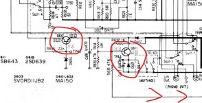
I am working on a Technics SL-10. I have gone through the unit and have identified a problem with the voltage supply on the MC amp section. I included a pic of the schematic section that I need help on. So the zener is a 9.1V which is supposed to be supplying the base of Q2 with 9.1V but the voltage I measure at the base is 8.2. This is not enough to get Q1 to supply 8.9V to the MC amp circuit. My amp circuit supply off Q1 emitter is 7.5V. I know enough to be dangerous here and I have changed out the zener with no change in the output voltage of Q1. I also changed out the Q2, the caps and 3.9K resistor in the immediate area. I lifted the emitter leg on Q1 and the voltage stayed at 7.5. I am sure my supply voltage is at 12V so that is not the problem. I am measuring about 3.1V across the zener so I know where the voltage is going but I can't understand why the zener is not doing its job and sending 9.1V to Q2's base. Can anyone advise me on what I am missing here? Thanks very much for helping!
I suspect it might be normal...
12 volts supply, 9v1 zener and a 3k9 series resistor. That means the Zener is operating at just 0.7 milliamps and so may well come in a bit low. Also Q2 (and Q1) form a Darlington pair and so will lose two 'Vbe volt drops' between the base of Q2 and the emitter of Q1.
So you could never get 8.9V from a 9V1 Zener, more typically 9V1 less 0.6 less another 0.6 giving 7.9 volts.
Its quite normal to find such discrepancies in older service manuals... don't worry. In fact if you look closely at the diagram you will see that they have shown Q2 emitter as being higher in voltage than the base.
As to your Zener, you could reduce the 3k9 a little to get a bit more voltage.
Finally are you sure Q1 and Q2 are good. If one is faulty or low gain/leaky then it will load the Zener more than normal while still otherwise appearing good. Those devices can be replaced by any generic equivalents.
Edit... circuit added. An alternative approach might be to use a 7809 regulator in place of the whole caboodle. It would simply fit in place of Q1. Remove the Zener and replace the resistor with a link to preserve decoupling. Don't forget the ground pin if you do that. That would be a much more stable supply all things considered.
Attachments

How does it *sound*?
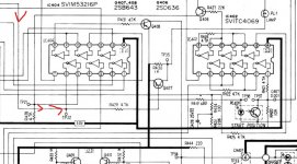
That circuit should be tolerant of supply voltage. Firstly, signals can't be over 1/10th Volt so a fraction of a Volt supply "could" work. Since plenty of voltage is available, they use more to make it very stable and robust.
If TP40 is over 1.0V, it's probably working fine.
If something else is sounding wrong, tell us.
Hi and thanks for the replies,
I will take all these great suggestions into account. Reduce the 3.9k to see about voltage increase, or put in the 7809 to see what happens. When I inject a sine wave through the inputs, I can see a fine signal all the way through the MC amp until the final resistor after the last cap in the signal path. It is significantly amplified as well. It just goes dead after the resistor at TP 41/42. I did replace all the lytics in the MC amp section as a PM or corrective measure. As you probably know, I cannot find out about my results until I re-assemble the TT so I wanted to make sure I have sufficient voltage on the supplies before doing so. I cannot find anything else to suspect for the problem. Before disassembly, the TT let sound through but it was very distorted but not necessarily diminished. I don't have a test tone record so all I had as a source was an album. What are the chances of the relay contacts being bad enough to cause distortion?
Ok then, back to the lab I go!🙂
Both channels can't be faulty and so I would concentrate on something pulling the signal down at those test points.
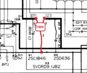
Is relay RL601 opening correctly?
This relay shorts the audio to ground when muting is required. The circuit is more complex than might be thought and as well as needing the correct supply (emitter of Q612) there is also a logic input operating on Q611.
Check that supply first though and determine whether the relay is 'unmuted' only when the coil is powered (most likely scenario).
If the problem is in the logic section then most likely would be an incorrect input from something mechanical rather than a component fault.
Attachments
Ok so here is what I found. TP40 and 39 are at 1.6V
Q611/612 are very close to spec voltages
I played around with resistances on R1 and even going down to 2.8k from 3.9 didn't make more than .1V difference.
So if I wanted to sub the 7809 for Q1 will the lower voltage on the ground pin act as a ground enough to get the 9V out? also what about q2 and all related devices to the supply to the MC amp section? Should I just remove them and tie a ground to the 7809?
I have voltage to the coil for the muting switch and TP42 is shorted to ground so if I disconnect power to the coil I should see output signal on the RCA jacks and TP42, right? Loong night in the lab so hope to hear from you tomorrow! Thanks!!!
That's right 🙂 if we are correct in assuming that the muting the works by having the coil powered but we just need to be 100% sure on that one. So if you have 10 to 12 volts across the coil (and in this state it shorts the outputs to ground) then isolating the coil will change the relay state and you should get audio.
Look at the circuit... if we apply a shorting link across R634 which is the 33k between base and emitter of Q611 then we turn OFF the power to the relay. As long as Q611 is good then that is a quick way of checking.
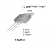
All the 78 series regulators have three pins, an input, an output and a ground. If you want to try this at some point then I'd also suggest looking at the caps on the input and output of the regulator. What you have will work but the optimum would be more in line with the data sheet... a couple of small film caps located right up close to the reg itself. Use the same ground points the existing components related to the transistor reg use.
I'd concentrate on fixing the relay first though.
HTTP 301 This page has been moved
Look at the circuit... if we apply a shorting link across R634 which is the 33k between base and emitter of Q611 then we turn OFF the power to the relay. As long as Q611 is good then that is a quick way of checking.
All the 78 series regulators have three pins, an input, an output and a ground. If you want to try this at some point then I'd also suggest looking at the caps on the input and output of the regulator. What you have will work but the optimum would be more in line with the data sheet... a couple of small film caps located right up close to the reg itself. Use the same ground points the existing components related to the transistor reg use.
I'd concentrate on fixing the relay first though.
HTTP 301 This page has been moved
Attachments

 YAY! Well shorting R634 worked, now I can chk my audio path from input to RCA out and it all looks great through the whole freq. range. So only one more thing remains before I put it all back together to have a listen. The voltage on the supplies for the MC amp. Do I put in the 7809, or stop chasing ghosts and just assume all is normal? I still get just over 7.5V on them.
Thanks Mooly and PRR and any other posters for all your help!

Excellent 
Its up to you if you want to investigate a different kind of regulator such as the 7809, or whether you might prefer to keep it all original.
The IC regulator should be much better technically, the only proviso (do you have a scope?) is that the input voltage including the dips in ripple voltage must always be above the minimum required which I think would be 11 volts for a 7809.
You could also try and see why the mute line is holding it in mute. As mentioned before, the first suspects would be to look at all the mechanical inputs to the mute circuitry as problems there are more likely than electronic component issues.
Hi Mooly,
The mute was not stuck on as part of the problems, but unless I can determine what action has to occur for the mute to turn off I was going to wait till the unit is together. It just prevented me from scoping from beginning to end of signal path during the repair process.
I do have a scope an1d will investigate the ripples and dips. The circuit is fed by a 7812 presently from a rectified 20V so I am thinking it should be ok but I will check. The owner just wants it to work and doesn't care about original parts. I will go that route. It is a small task to get this thing apart so I do not want to do it again for the sake of that circuit voltage.
I will let you know how it goes.
BTW, you said put some film caps in the 7809 circuit. I have a large assortment of different caps both polar and non in different values. Is film, the technical name for that one or is that a general term? I can look it up to see what it looks like. I imagine it does not have to be fancy for a 7809 application, right?
I am really looking forward to getting this off my bench, I have lots of patients in the waiting room.
If its a repair job then I'd probably leave it in its original form tbh. There's not much point you tweaking it in this situation. I thought it was yours 🙂
Film caps are normally mylars and poly/props/styrenes etc. Ceramics can be good to for general purpose regulator decoupling. Electrolytics have rising impedance at very high frequency which negates their wanted effect.
If a 7812 feeds the discrete regulator then there is not going to be any measurable ripple. I'll be honest, I hadn't looked at how the 12 volts was initially derived. On that basis I'd perhaps leave it original.
Ok Mooly, it belongs to a good friend and I am doing it as a favor. I have to live with the results for years to come so I am treating it like mine. I don't repair for a living, I do it as a hobby but I guess I am kind of a serious tinkerer as I have many pieces of equipment in what we affectionately call the dungeon (lab). After this is done, I am going to seriously begin to work on understanding semi-conductors by building (and perhaps blowing up🙄) some things. I used to work at Philips so I am well stocked with supplies. I just really want to understand this stuff to make it easier to diagnose and repair my vintage amps receivers, etc. I appreciate this group and the all the contributors!😀
That sounds fair enough 🙂 and you can't beat building stuff and occasionally letting the magic smoke free.
Hey Mooly,
Strange but the 7809 regulator only brought the voltage up to 8V and not 9.. I thought the term "regulator" means it maintains 9V. Anyway, I took it as a win and assembled the TT and it works great!!
Hi five to you and the other helpers in the group! 😀
Thanks very much. Now I have to decide what to put up next, but I am gonna get my learn on too.😎
I am sure this is not the last you will hear from me as I have many, many projects to work on here😱
Later guys!
It should really be nearer 9 than 8 😉 but as long as there was enough voltage going to it then it should be fine... and with a 7812 feeding it then there would be more than enough.
Sounds like you are planning having some fun with whatever projects you have up your sleeve. You know where we are 🙂
Sounds like you are planning having some fun with whatever projects you have up your sleeve. You know where we are 🙂
- Home
- Design & Build
- Construction Tips
- Please help with a circuit issue