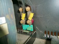
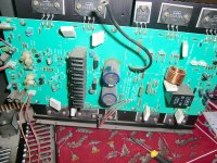
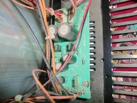
I opened up my amp and noticed a mini-PCB board attached to output channels,
Could somebody please help me figure out what this is for exactly and what does it do to the sound quality ?
It has a resistor and small capacitor attached,
Resistor = 3W_10ohm
metallized paper capacitor = 250V/0.1 microfarads?
(pictures included)
Could somebody please help me figure out what this is for exactly and what does it do to the sound quality ?
It has a resistor and small capacitor attached,
Resistor = 3W_10ohm
metallized paper capacitor = 250V/0.1 microfarads?
(pictures included)
Attachments
99% of transistor amplifiers have this on the main PCB, it keeps a resistive load on the amplifier at high frequencies for stability. Do NOT remove it.
Do you think replacing this mini-capacitor and resistor with higher quality equivalents would produce higher quality high frequency spectrum ?
Is there a way to improve the current schematic configuration with slightly different values/parts ?
Is there a way to improve the current schematic configuration with slightly different values/parts ?
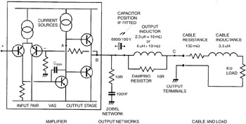
No. Leave it as it is. As davidsrb said, it is simply there to ensure the amp sees a resistive load at high frequencies (i.e. well above the audio range).
order of magnitude estimates:
0.1 uF Zc @ 16kHz ~ 100j Ohms
Zout amp w/damping factor 100, designed for 8 Ohm nominal load ~100 milliohm
attenuation factor ~ 1000:1, -60 dB
any "error" of the capacitor will be diminished by 60 dB at high audio frequencies, the attenuation factor goes up ~linearly as frequency goes down
you can look up "Capacitor Distortion", likely the box cap in the picture is at least Mylar film
dielectric absorption, loss are mostly linear, finding actual nonlinear distortion in Caps isn't easy
but if it were even 0.1% then the -60 dB estimated above gives effects at -120 dB at the top of the audio range
if any estimate above were even 10x off you still wouldn't expect to hear the error products alone in a common home listening room
Ok, could somebody simply help to figure out what frequency range does this particular mini-PCB affect ?
Is it exerting 100% affect above 22khz and 0% below 22khz ?
Or how can we calculate this ?
Is it exerting 100% affect above 22khz and 0% below 22khz ?
Or how can we calculate this ?
It doesn't quite work like that. The amplifier is assumed to be a 'voltage source' over the audio band, and the effect of this network has no impact in that sense.
The network appears as a progressively lower impedance the higher the frequency. That 'effect' starts from as low a frequency as you care to imagine. Its progressive. There is no sudden yes its doing something, no its not.
The network appears as a progressively lower impedance the higher the frequency. That 'effect' starts from as low a frequency as you care to imagine. Its progressive. There is no sudden yes its doing something, no its not.
The frequency at which the network is doing half its job is given by f = 1/(2 pi R C). It will be doing essentially nothing at 10% of this frequency, and doing essentially the whole thing above 10x the frequency. For 10R and 0.1uF, f = 160kHz.
I don't think any theoretical argument is going to satisfy the OP other than to say the product wasn't competently engineered and this is how a remedy was attempted. The fact that the network has not been fitted right at the power amplifier itself says it needed a fix and probably after production began. The questionable feature is the location.
Output Networks | IHS Engineering360
There's no mention of make or model so no way to check what other arrangements for stability of the amplifier may have been made. How about a little more detail?
Output Networks | IHS Engineering360
There's no mention of make or model so no way to check what other arrangements for stability of the amplifier may have been made. How about a little more detail?
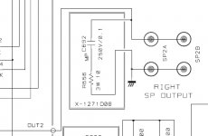
Here is the complete Technical manual for Rotel 1090-RB
This amp was designed quite a few years ago,
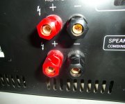
The mini-PCB is at the channel outputs
From today's engineering point of view, - which improvement would one do to this board first and foremost ?
And Which capacitors/resistors to replace with higher quality for significant effects ?
This amp was designed quite a few years ago,
The mini-PCB is at the channel outputs
From today's engineering point of view, - which improvement would one do to this board first and foremost ?
And Which capacitors/resistors to replace with higher quality for significant effects ?
From today's engineering point of view, - which improvement would one do to this board first and foremost ?
On that small board ?
None... the components have no effect on the audio quality the amp delivers.
I have a picture of the actual board for each channel + schematic,
Is there anyone here who up to the challenge of trying to give today's engineering recommendations towards improving the circuit ?
(Even if it only is about which Capacitors and Resistors to upgrade)
Is there anyone here who up to the challenge of trying to give today's engineering recommendations towards improving the circuit ?
(Even if it only is about which Capacitors and Resistors to upgrade)
Attachments
I have a picture of the actual board for each channel + schematic,
Is there anyone here who up to the challenge of trying to give today's engineering recommendations towards improving the circuit ?
(Even if it only is about which Capacitors and Resistors to upgrade)
It looks like a decent amp. Sanken transistors.
If it's 15 years old or more, and you really want to play with it, perhaps you could replace electrolytic capacitors with new ones...
which improvement would one do to this board first and foremost ? Which capacitors/resistors to replace
with higher quality for significant effects ?
I'd check the resistors' values, as they are not normally sized for high power operation and may be substantially off,
if the amplifier was run at higher levels often.
The Zobel
I will tell you what I will do with the zobel, but first I will explain the situation...
The zobel has several functions, mostly to increase the safety factor of the amplifier driving difficult load (usually capacitive), or zero load...
What is the basic safety/stability level without the zobel? It is unknown, you have to study the circuit and it's implementation, as it is the property of the design itself...
If the amp is perfectly stable with zero ohm or with capacitive load, the zobel has less value...
A non-stable amp is not a good design, so I would say that a good amp should not be highly dependent on the zobel to operate flawlessly (As long as we treat the system with "care").
If the amp has serious stability issue, the zobel should have been fitted closer to the amp (not in binding posts) and the value is usually smaller in R and bigger in C and have higher working frequency. So, from the look of it, the zobel must play non-critical function for the amplifier stability, so we can safely "modify" the zobel to our needs...
I will prefer to increase the working frequency by changing the C to a lower value (such as 33n), such that it will not interfere with the audible frequency. The zobel should not affect phase at 20kHz. This is based on my assumption (which I believe so) that it should be audible...
Now the question is, is it audible? What kind of audibility?
If you think you can hear it in an ABX, then I will bet my money that you wont be able to hear it. But if you want to put your money that I will not be able to hear it, then I'm in and ready for it 🙂
The sound change can be positive or negative, depends on preference and the condition of the tweeter and recording. If the HF quality is not good (due to recording or interference or tweeter/crossover) it is usually better to lower the impedance using bigger C (100n in this case). But for musicality, I believe that good phase should be maintained.
Is there anyone here who up to the challenge of trying to give today's engineering recommendations towards improving the circuit ?
(Even if it only is about which Capacitors and Resistors to upgrade)
I will tell you what I will do with the zobel, but first I will explain the situation...
The zobel has several functions, mostly to increase the safety factor of the amplifier driving difficult load (usually capacitive), or zero load...
What is the basic safety/stability level without the zobel? It is unknown, you have to study the circuit and it's implementation, as it is the property of the design itself...
If the amp is perfectly stable with zero ohm or with capacitive load, the zobel has less value...
A non-stable amp is not a good design, so I would say that a good amp should not be highly dependent on the zobel to operate flawlessly (As long as we treat the system with "care").
If the amp has serious stability issue, the zobel should have been fitted closer to the amp (not in binding posts) and the value is usually smaller in R and bigger in C and have higher working frequency. So, from the look of it, the zobel must play non-critical function for the amplifier stability, so we can safely "modify" the zobel to our needs...
I will prefer to increase the working frequency by changing the C to a lower value (such as 33n), such that it will not interfere with the audible frequency. The zobel should not affect phase at 20kHz. This is based on my assumption (which I believe so) that it should be audible...
Now the question is, is it audible? What kind of audibility?
If you think you can hear it in an ABX, then I will bet my money that you wont be able to hear it. But if you want to put your money that I will not be able to hear it, then I'm in and ready for it 🙂
The sound change can be positive or negative, depends on preference and the condition of the tweeter and recording. If the HF quality is not good (due to recording or interference or tweeter/crossover) it is usually better to lower the impedance using bigger C (100n in this case). But for musicality, I believe that good phase should be maintained.
The Amplifier
I like the schematics of the amplifier. The transistors are also of very good quality. But like many commercial designs, the wiring and layout is not optimum. The wiring is messy...
From today's engineering point of view, - which improvement would one do to this board first and foremost ?
And Which capacitors/resistors to replace with higher quality for significant effects ?
I like the schematics of the amplifier. The transistors are also of very good quality. But like many commercial designs, the wiring and layout is not optimum. The wiring is messy...
The capacitors
I don't think the amp is old enough to replace the caps. Caps can last more than 10 years...
I don't know why the on-board bypass capacitor (1000uF/100v) visually doesn't look better than capacitors on cheap Sony amps... I use Black Gates for this kind of bypass... But may be the difference is not much (soundwise).
But the input capacitor is not good. Polarized 4.7uF/50V. It is strange that amp of this caliber uses non bipolar capacitor for the input. BP cap is not expensive but the sound is IME better than polar caps (My favorite is Black gate N).
Feedback cap, 100uF/25, can be higher capacitance with lower voltage to keep size small. I use Sanyo OSCON for this purpose. The improvement might be less than the input cap upgrade...
BTW, how do you like the sound of this amp?
Last edited:
The engineering recommendation is to correct any faults, then leave it alone. 'Upgrading' components is not what engineers do, as they know it makes no difference (apart from your wallet).Herbgarden said:Is there anyone here who up to the challenge of trying to give today's engineering recommendations towards improving the circuit ?
(Even if it only is about which Capacitors and Resistors to upgrade)
In order to improve a circuit you first need to understand it even better than the original designer. For an expert reviewing a bad circuit this can take a few minutes, maybe an hour; for a newbie reviewing a competent circuit this can take about a decade, so most skip this step and just 'upgrade' components instead.
- Status
- Not open for further replies.
- Home
- Amplifiers
- Solid State
- Please help to figure out - mini-PCB attached to Amp-Output