Hi Folks,
I tried finding the answer to this question but couldn't and asked within another thread but didn't get an answer.
I'm really stuck on this basic question "can software (I'm using PCD7.0) accurately predict the phase response of a system".
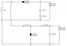
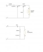
The reason I'm asking is I designed my speaker, 2 way, Vifi tweeter and Peerless woofer, I used PCD to design a linkwitz-riley 2nd order. I got it to what I thought was the best point for a good transition, 1.33mH/5.1uF on the woofer and 10uF/0.68mH on the tweeter with a zobel on the woofer and an optional L-pad on the tweeter. (sorry I can't figure out how to print out a schematic of the crossover)
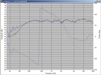
On examining the phase, reversing the phase on the tweeter seemed to give the best response, the phase was a slow slope from low to high frequency with no abrupt changes. Attached on the first screen grab is my crossover. Grey is phase sum, orange and blue are driver phases.
However I built the crossover a day or so ago and tried out the speakers, there is bass and treble but it seems like not much in the middle 🙁 (maybe I should run for a week to burn in?)
Soooo I hooked up an oscilloscope to the output of the tweeter and woofer, when I run a sine wave through the system at the predicted crossover frequency the two responses are almost completely out of phase, so it looks like I'm getting destructive interference which explains why my speakers don't seem to have much 'middle'.
First of all why is this? does this mean the PCD tool cannot actually predict the correct phase response?
I've heard people on the forum talk about flipping the terminals around to try it both ways and see which sounds best, but why do this? If the software can model the response surely it is better than trial and error?
I have tried searching on here and google to find an answer on what is considered a 'good' phase response on a crossover (obviously flat is best but not usually possible) but can't see to find this. Any help is appreciated!
Chris
I tried finding the answer to this question but couldn't and asked within another thread but didn't get an answer.
I'm really stuck on this basic question "can software (I'm using PCD7.0) accurately predict the phase response of a system".
The reason I'm asking is I designed my speaker, 2 way, Vifi tweeter and Peerless woofer, I used PCD to design a linkwitz-riley 2nd order. I got it to what I thought was the best point for a good transition, 1.33mH/5.1uF on the woofer and 10uF/0.68mH on the tweeter with a zobel on the woofer and an optional L-pad on the tweeter. (sorry I can't figure out how to print out a schematic of the crossover)
On examining the phase, reversing the phase on the tweeter seemed to give the best response, the phase was a slow slope from low to high frequency with no abrupt changes. Attached on the first screen grab is my crossover. Grey is phase sum, orange and blue are driver phases.
However I built the crossover a day or so ago and tried out the speakers, there is bass and treble but it seems like not much in the middle 🙁 (maybe I should run for a week to burn in?)
Soooo I hooked up an oscilloscope to the output of the tweeter and woofer, when I run a sine wave through the system at the predicted crossover frequency the two responses are almost completely out of phase, so it looks like I'm getting destructive interference which explains why my speakers don't seem to have much 'middle'.
First of all why is this? does this mean the PCD tool cannot actually predict the correct phase response?
I've heard people on the forum talk about flipping the terminals around to try it both ways and see which sounds best, but why do this? If the software can model the response surely it is better than trial and error?
I have tried searching on here and google to find an answer on what is considered a 'good' phase response on a crossover (obviously flat is best but not usually possible) but can't see to find this. Any help is appreciated!
Chris
Attachments

What kind of data you inputted in the simulator?"can software (I'm using PCD7.0) accurately predict the phase response of a system".
Did you used the frd/zma's?
(I don't know that version/simulator) But does it work with phase and drivers phase?
The easy answer/fix to your problem is just invert the connection to have same phase. If you want to model phase, as you should with any good simulator, you need to insert the phase data in the model and have it compound for output.
You can not simulate a good passive crossover if you are not using the differences of phase between drivers, and components, plus their time alignment and position in space/baffle in relation to each other.
Last edited:
You don't use Zobels on paper woofers in practise. They only have a place with plastic cones and low order filter rolloff.
You've come a long way from Veeper's 1.5mH/10uF bass suggestion, never mind the tweeter circuit for a regular 6 ohm DC dome:
Veeper TM Monitor
The Peerless 830875 0.41mH Nomex woofer is a tricky unit with its 4kHz peak, but I don't think a Zobel is helping at all. It's probably rolling off the midrange too much.
PEERLESS-NOMEX-164
You'd probably do well to get more conventional here. FWIW, 2nd. order circuits on flat baffles always have the drivers in phase. That's how it is. Neither circuit below appeals to me much, but should be OK as a starting point. The object is to align the phase of the two drivers as best you can. 🙂
Attachments

What's probably happening is that it is the acoustic offset between the drivers causing the phase difference.
Unless the software has an explicit input to correct for this it assumes that both drivers are radiating from the same acoustic plane, as they are for instance for the ideal L-R characteristic.
rcw
Unless the software has an explicit input to correct for this it assumes that both drivers are radiating from the same acoustic plane, as they are for instance for the ideal L-R characteristic.
rcw
Good phase? Start by lining the drivers up around the crossover, this is the main issue.
Phase will vary as you move around and since the drivers are not in the same location as each other they'll be 'in' or 'out' at different places. Manipulating this is really on another level though and I was just hoping to put the single 'phase plot' in to perspective. I like to move a mic up and down in front of a speaker just to double check I haven't messed anything up. (Do a search on Speaker Dave and pink noise for a non-mic method.)
PCD can determine phase to a point. If you use your drivers within their limits and take in to account their distances from you then you may get a usable design, but I'd rather measure them.
Sure software can sim the phase. Please see below the simulated (black) and measured response (blue) for my 4th order bessel crossover. (crossover at 2.8Khz)
Note that the actual measurement was done months after the original individual driver measurements at a slightly different distance, in a different location. It was also done without as much care as the original measurements. If I were to measure the individual drivers again, and then without moving anything, measure the final crossover, and then sim and compare, the differences would be much smaller.
Tony.
Attachments
What kind of data you inputted in the simulator?
Did you used the frd/zma's?
(I don't know that version/simulator) But does it work with phase and drivers phase?
The easy answer/fix to your problem is just invert the connection to have same phase. If you want to model phase, as you should with any good simulator, you need to insert the phase data in the model and have it compound for output.
You can not simulate a good passive crossover if you are not using the differences of phase between drivers, and components, plus their time alignment and position in space/baffle in relation to each other.
I got the driver responses from here:
Driver FRD & ZMA files
You don't use Zobels on paper woofers in practise. They only have a place with plastic cones and low order filter rolloff.
You've come a long way from Veeper's 1.5mH/10uF bass suggestion, never mind the tweeter circuit for a regular 6 ohm DC dome:
Veeper TM Monitor
The Peerless 830875 0.41mH Nomex woofer is a tricky unit with its 4kHz peak, but I don't think a Zobel is helping at all. It's probably rolling off the midrange too much.
PEERLESS-NOMEX-164
You'd probably do well to get more conventional here. FWIW, 2nd. order circuits on flat baffles always have the drivers in phase. That's how it is. Neither circuit below appeals to me much, but should be OK as a starting point. The object is to align the phase of the two drivers as best you can. 🙂
Thanks, I'll try putting them in my sim and seeing what the output looks like 🙂
I didn't realize zobels weren't used under certain conditions, in my sim it seemed to help flatten the frequency response, but I'll take it out.
Last edited:
Good phase? Start by lining the drivers up around the crossover, this is the main issue.
Phase will vary as you move around and since the drivers are not in the same location as each other they'll be 'in' or 'out' at different places. Manipulating this is really on another level though and I was just hoping to put the single 'phase plot' in to perspective. I like to move a mic up and down in front of a speaker just to double check I haven't messed anything up. (Do a search on Speaker Dave and pink noise for a non-mic method.)
PCD can determine phase to a point. If you use your drivers within their limits and take in to account their distances from you then you may get a usable design, but I'd rather measure them.
Yeah I can absolutely hear high and low spots. I took one of my speakers and reversed the tweeter around (in phase with the woofer) when sat quite close I can move my head around and at the crossover frequency the output goes up and down, its quite amazing how low it drops in some places.
I also made an ESP preamp mic with high quality components for measurements but I don't have one of those panasonic flat frequency response electrets for it yet, I'll get one ordered and I should be able to take some basic measurements.
Last edited:
There is a place in PCD to input driver offset. Whether you put the offset there or use the measurements to capture the offset, the software needs to have it in there to predict phase correctly. What this means is that, sometimes you can capture the driver offset through the measurement. HolmImpulse lets you fix the time on one measurement and then draws the phase of subsequent measurements based on the fixed one. This is an easy and accurate way to do it. If this is not done, then you need to enter the offset in PCD.
Yes, you need to put the real z-offset into PCD accurately to sim phase alignment, or include the offset in your measurements. Determining the offset with a mic is quite easy, so you'll be off and running soon.
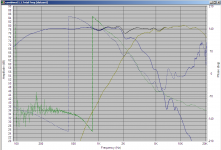
Btw, not that it matters since the sim wasn't valid, but your phase tracking isn't very good in that sim. You want the individual driver phase plots to be on top of each other at the crossover point (when you've set all the offsets relative to your design axis, which is generally the midpoint between driver centers for a 2-way), and preferably to stay aligned for quite a while in either direction. Your graph shows the drivers 30-60° out of phase in the crossover region.
Bart,
I don't know where the statement about not using a zobel network on a paper cone is coming from. but it doesn't make any sense to me and what the cone material is is irrelevant to the impedance rise of the driver. That is not the cause of your problem if it was implemented correctly. Seems more likely that you have chosen the crossover values incorrectly. I would however not use a 2nd order crossover unless you do expect to have poor phase alignment between the two devices. One of the worst crossover topologies you could chose to use. Get yourself a copy of Douglass Self on active crossovers, it does talk about passive issues. I would read that before you go much further down this road. Only reason to use 2nd order is trying to cut costs or simplicity, but it is a lousy choice in my opinion. If you have the amplifier power then a passive 4th order crossover is the preferred choice.
I don't know where the statement about not using a zobel network on a paper cone is coming from. but it doesn't make any sense to me and what the cone material is is irrelevant to the impedance rise of the driver. That is not the cause of your problem if it was implemented correctly. Seems more likely that you have chosen the crossover values incorrectly. I would however not use a 2nd order crossover unless you do expect to have poor phase alignment between the two devices. One of the worst crossover topologies you could chose to use. Get yourself a copy of Douglass Self on active crossovers, it does talk about passive issues. I would read that before you go much further down this road. Only reason to use 2nd order is trying to cut costs or simplicity, but it is a lousy choice in my opinion. If you have the amplifier power then a passive 4th order crossover is the preferred choice.
^dumptruck +1 This is where the simulation can really help. Relatively minor changes in C or L values can improve the phase tracking without having any noticable effect on the individual drivers rolloffs. Changing values and seeing what effect they have in a sim is a lot easier than doing it with real components and measurements.
pic attached showing the individual phase of the drivers for the example I posted earlier showing good phase tracking through the crossover region. It took quite a bit of fiddling in the sim to get it to this. But if your measurements are good, then the sim should be too. I got in the ballpark with PCD then switched to speaker workshop for fine tuning.
Tony.
Attachments
You still can if it makes life easier, especially during the development process.I didn't realize zobels weren't used under certain conditions,
Generic FRD files may be made without baffle conditions, such as on a large flat board, or at least maybe on a different baffle to yours so you may want to check that. I've also seen them without phase information (zeroed), especially the ZMA files. Open them in a text editor to check this.I got the driver responses from here:
If you can get these nulls to sit above and below your listening position, and confirm this using several tones an octave either side of the crossover then you should be on the right track.when sat quite close I can move my head around and at the crossover frequency the output goes up and down, its quite amazing how low it drops in some places.
^dumptruck +1 This is where the simulation can really help. Relatively minor changes in C or L values can improve the phase tracking without having any noticable effect on the individual drivers rolloffs. Changing values and seeing what effect they have in a sim is a lot easier than doing it with real components and measurements.
pic attached showing the individual phase of the drivers for the example I posted earlier showing good phase tracking through the crossover region. It took quite a bit of fiddling in the sim to get it to this. But if your measurements are good, then the sim should be too. I got in the ballpark with PCD then switched to speaker workshop for fine tuning.
Tony.
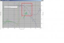
Ok I think I get this more now, so the region in the red box which is the crossover region the individual phase both have slopes but are almost on top of each other so no cancellation?
Edit- I've drawn up my original crossover and attached it.
Attachments
Last edited:
Good point. If using frd/zma's and they are incomplete. 🙁...without phase information (zeroed), especially the ZMA files. Open them in a text editor to check this.
wintermute, GOOD phase tracking in your example and I would not expect big/any problems in output. A big null can be the signal of a phase match "on the other side" for Chris.
Maybe it's time someone (give it a hand and) check his crossover (I have no ideas of the drivers he's using and what he's doing). 😱
Yep. Here's a PCD example for you. You've still got to get the acoustic offset settings in PCD pretty close to reality for it to measure as simulated, though.Ok I think I get this more now, so the region in the red box which is the crossover region the individual phase both have slopes but are almost on top of each other so no cancellation?
Attachments
Ok how does this look?
I spent some time tweaking and adjusting, I now have a 2nd order on the woofer and a 3rd order on the tweeter with an L-pad for some attenuation.
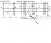
I adjusted the values until I got a relatively smooth frequency response and the phase slopes of the two drive units basically line up as shown by the big green arrow. Does the fact the point where the phase seems to abruptly change almost line up with my crossover point matter?
Feedback greatly appreciated, I hope I'm getting closer guys!
Chris
I spent some time tweaking and adjusting, I now have a 2nd order on the woofer and a 3rd order on the tweeter with an L-pad for some attenuation.
I adjusted the values until I got a relatively smooth frequency response and the phase slopes of the two drive units basically line up as shown by the big green arrow. Does the fact the point where the phase seems to abruptly change almost line up with my crossover point matter?
Feedback greatly appreciated, I hope I'm getting closer guys!
Chris
Attachments
- Status
- Not open for further replies.
- Home
- Loudspeakers
- Multi-Way
- Please help, really stuck on phase :(