Hi, All
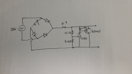
I build a simple schematic using TL431 but my transistor run hot and the output voltage isn't reach what i want. Can anyone help on this? Below is my schematic.
I had source 25v AC and i need Vout =20v Iout = 60ma
When i power up the circuit below. Vout = 16v and Transistor run hot in few sec. if i add 10uf after the transistor it come out 18v but transistor run hot as well.
Thanks if anyone can help.
Attachments
my transistor run hot and the output voltage isn't reach what i want.
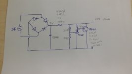
The TL431 device current must be >1mA, so decrease the 2.4k resistor's value to <600R
so that it can regulate properly. A value of 200R will set the TL431 current to 3mA.
When operating as intended, the current through the 62R is about (35V-20V)/62 = 242 mA.
Power dissipated by Q ~ (20V x 0.239A) = 4.8W. That will be hot, so use a good heat sink.
Power dissipated by 62R = (15V x 15V)/62R = 3.6W. That will be hot, so use a 10W resistor.
Last edited:
It really wants a cap after the rectifier; otherwise the output is pulsating NOT steady as you want.
With a "small" (100uFd) cap the output may be nearer 29V than 35V.
I get slightly lower heat numbers than rayma calculated. Depends what first cap you use, and PT parameters.
In any case, the big R is passing a LOT more than the 60mA you need. You do need "more", but 3X-4X more seems excessive. All that excess has to be absorbed by the BD140. 2 to 5 Watts is Too Much for a power transistor with no heatsink. Also the "61.9r" is around 2 Watts (while load power is only 1.2W).
Make the "61.9" much larger, over 100 Ohms. This is a balancing act; too large will not be good. 200 Ohms is too large. A second 61.9 in series may be an easy hack?
A 7815 or LM317 can be shimmed to 20V and will not have the large excess current/heat of this shunt regulator. I also suspect it has better ripple rejection here on raw DC. Shunt regulators normally go after some brute-force regulator or massive passive filter. For loads approaching a Watt, shunt regulators are always "hot".
Attachments
It really wants a cap after the rectifier; otherwise the output is pulsating NOT steady as you want.
Good call on the input cap, didn't even notice. I guessed at 35VDC for the input voltage.
Based on 1000uF/Amp, I'd use more than 250uF for the input cap. The 2.4k is too large, though.
Last edited:
It really wants a cap after the rectifier; otherwise the output is pulsating NOT steady as you want.
With a "small" (100uFd) cap the output may be nearer 29V than 35V.
I get slightly lower heat numbers than rayma calculated. Depends what first cap you use, and PT parameters.
In any case, the big R is passing a LOT more than the 60mA you need. You do need "more", but 3X-4X more seems excessive. All that excess has to be absorbed by the BD140. 2 to 5 Watts is Too Much for a power transistor with no heatsink. Also the "61.9r" is around 2 Watts (while load power is only 1.2W).
Make the "61.9" much larger, over 100 Ohms. This is a balancing act; too large will not be good. 200 Ohms is too large. A second 61.9 in series may be an easy hack?
A 7815 or LM317 can be shimmed to 20V and will not have the large excess current/heat of this shunt regulator. I also suspect it has better ripple rejection here on raw DC. Shunt regulators normally go after some brute-force regulator or massive passive filter. For loads approaching a Watt, shunt regulators are always "hot".
PRR and Rayma
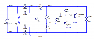
Combine both of you suggestions, i had redraw the schematic please help to check whether this calculation and schematic will work in the right operating point. I plan not using the heatsink on the Q
As Q will work around 3.8-4ma if i assume the VBE 0.7v
and the Q with no load will be around 1.5w
Does this workable and did all the calculation correct?
Thanks
Attachments
Does this workable and did all the calculation correct?
Seems ok, I think the input voltage will be higher, even with the small 100uF input capacitor.
Measure it and see.
Mark, those clever net names will fly over these young whipper-snappers' heads
😀
mlloyd1
😀
mlloyd1
In my opinion it will be safer to include explicit frequency compensation as shown.
_
I agree. The 25Vac transformer is likely to give 31Vdc only when mains is at -6%.Seems ok, I think the input voltage will be higher, even with the small 100uF input capacitor.
Measure it and see.
When mains is at maximum of +6%, the average voltage on the first smoothing cap is likely to be over 35Vdc. Maybe even as high as 37Vdc.
That resistor wiil need to dissipate a lot more power. Then the Shunting Q will have to dissipate all the extra current that does not get used.
Maybe replace the 150r resistor with a 317 configured as a Constant Current Source set to ~80mA (16r in the output lead).
0.8mA through the resistor string, 2.2mA through the 431, 16mA through the shunt Q and 61mA to the load.
The load current can vary by +-15mA and the shunt will still operate.
Use heatsinks !
Last edited:
- Status
- Not open for further replies.
- Home
- Amplifiers
- Power Supplies
- Please help on TL431 schematic