You are trying to convert class AB2 amp.
If you want cathode bias, you need to design a new amp that works in class A1.
However, people gave you many suggestions how to do that, it is theoretically possible, but it is useless. If to convert it into class A1, cathode followers are not needed at all. They even do harm, charging coupling capacitors faster on overload.
You need higher idle current, so both tubes run without cut-off all the way, in order for self-bias to work. And lower B+ voltage, to keep tubes below their rated max anode dissipation power. That means, you need also output transformer designed for that.
...and remove Yves Monmagnon's name from the drawing, so he would not be responsible for dynamic distortions caused by bias following by signal envelope.
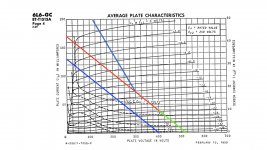
You have the correct V/I curve for 6L6. One correct way to draw a load line is to draw a line from 400V to 133mA. This is a 3K load line (each 6L6 see half of the 6K output transformer). The133mA value came from 400V/3K. Once your draw that line, move that line up vertically by 40mA (your planned bias). Move the lower point to 40mA, upper point of the line to 133+40mA=173mA. Now extend the lower end of the line to 0 mA following the same line slop. This line now represent the AC loading that each 6L6 will see with a 6 ohms resistive output load when the amp is in class A.
The bias point is the intersection of 40mA and 400V on the load line. Grid voltage should be near -22V.
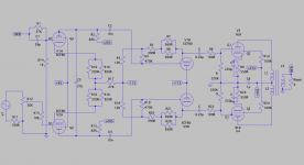
Thank you so much for being so patient! I've redrawn the schematic and the load line. step 1, is blue step 2, is red step 3 is green. I think I'm beginning to understand this but I'm a long way from drawing my own output stage....
You are trying to convert class AB2 amp.
If you want cathode bias, you need to design a new amp that works in class A1.
However, people gave you many suggestions how to do that, it is theoretically possible, but it is useless. If to convert it into class A1, cathode followers are not needed at all. They even do harm, charging coupling capacitors faster on overload.
You need higher idle current, so both tubes run without cut-off all the way, in order for self-bias to work. And lower B+ voltage, to keep tubes below their rated max anode dissipation power. That means, you need also output transformer designed for that.
I asked IF this was possible. It was made clear what the difference was. As said before, I decided to just build it as it was intended.
I also got an answer and tried to rework the schematic, while doing this the topic changed in making my dumb @ss understand the load line.
...and remove Yves Monmagnon's name from the drawing, so he would not be responsible for dynamic distortions caused by bias following by signal envelope.
I didn’t do so. But feel free to ask a moderator to change this because I can not.
Attachments

mrneedle,
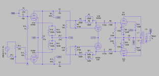
Your schematics in Post # 13, and # 24 show +65V on the Control Grid (nearest the cathode).
And they show Signal drive, and Negative Feedback drive to the Screen Grids (between
the Plate and the Control Grid).
Needs correcting.
I guess nobody caught it (and me too).
Your schematics in Post # 13, and # 24 show +65V on the Control Grid (nearest the cathode).
And they show Signal drive, and Negative Feedback drive to the Screen Grids (between
the Plate and the Control Grid).
Needs correcting.
I guess nobody caught it (and me too).
Last edited:

I would put in pin numbers in the drawing. The way you draw it V1a and V2a, Grid and G2 still look reversed. As say in #25, input went to G2 and G2 voltage went to Grid instead .
Also to complete your load line drawing excises, here is the rest of the Class AB output load. Notice, there is a 1/2 of 3K (1.5K) load transition on the curve where one of the push pull output pentode begin to shut down. Approximately the mirror location when grid goes very negative (~ -32V and beyond).
Attachments
I would put in pin numbers in the drawing. The way you draw it V1a and V2a, Grid and G2 still look reversed. As say in #25, input went to G2 and G2 voltage went to Grid instead .
Also to complete your load line drawing excises, here is the rest of the Class AB output load. Notice, there is a 1/2 of 3K (1.5K) load transition on the curve where one of the push pull output pentode begin to shut down. Approximately the mirror location when grid goes very negative (~ -32V and beyond).
Again thank you for your time, explanation and patience. In the mean time I've ordered a tube amp building book that should prevent further uneducated questions.
cheers.
Attachments
I also missed your error of the order of grids on the 6L6 output tubes.
Again, the grid that is closest to the cathode, pin 8 is the Control Grid, pin 5 (normally for signal input).
And the grid that is between the Control Grid, pin 5 and the Plate, pin 3 is the Screen Grid, pin 4.
Normally, for a Pentode or for a Beam power tube the schematic should show either the Suppressor Grid, or Beam Forming Plates (between the Screen Grid and the Plate).
I agree, it is also important to number the pin numbers.
The above will help less knowledgeable builders to get the connections right.
I once wired a 7591 wrong (used the 6L6 pin configuration). Fortunately, the only thing that was hurt was a 1k Ohm resistor.
Last edited:
...dynamic distortions caused by bias following by signal envelope.
It will work in AB1, up to a somewhat lower power than it did when driven AB2. The clipping will be typical hi-fi tube-amp clipping, nothing horrible.
I do dislike hacking a design and losing the power *designed into it*. But the OP is insistent that this is what he has to do, because it calls for the parts he has in hand.
But there are simpler ways to push two 6L6 into 6K with cathode bias.
- Status
- Not open for further replies.
- Home
- Amplifiers
- Tubes / Valves
- please help me walk through the steps to convert to cathode auto bias