Hi all
My first post here and I look forward to participating in this forum, at least as best I am able to with my limited knowledge!
My apologies for the rather elementary question but I am trying to understand whether a power supply for a tube preamp I have can accommodate powering another 12ax7 tube.
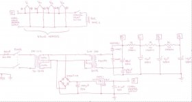
My schematic is attached for the power supply I have (240 volt primary). It currently powers 4 x 12ax7 valves in an existing guitar preamp. For tone reasons I want to build another preamp circuit and I need to power another 12ax7 tube for this new circuit. I am hoping I can power this extra 12ax7 from the existing power supply rather than having to make another one.
As I see it, there are two issues for the tube;
a) The first is whether there is enough current supplied for the 12 volt heaters to handle the current draw of another 12ax7; and
b) The other issue is whether I can use the existing HT supply to deliver about 280-300vdc to the new 12ax7's plate. In this regard, my thinking is I may need to add another capacitor and resistor to the network already there but am slightly confused with how to calculate those values correctly.
If any of you guys could assist me and help me learn I would be so appreciative.
Cheers and thanks
My first post here and I look forward to participating in this forum, at least as best I am able to with my limited knowledge!
My apologies for the rather elementary question but I am trying to understand whether a power supply for a tube preamp I have can accommodate powering another 12ax7 tube.
My schematic is attached for the power supply I have (240 volt primary). It currently powers 4 x 12ax7 valves in an existing guitar preamp. For tone reasons I want to build another preamp circuit and I need to power another 12ax7 tube for this new circuit. I am hoping I can power this extra 12ax7 from the existing power supply rather than having to make another one.
As I see it, there are two issues for the tube;
a) The first is whether there is enough current supplied for the 12 volt heaters to handle the current draw of another 12ax7; and
b) The other issue is whether I can use the existing HT supply to deliver about 280-300vdc to the new 12ax7's plate. In this regard, my thinking is I may need to add another capacitor and resistor to the network already there but am slightly confused with how to calculate those values correctly.
If any of you guys could assist me and help me learn I would be so appreciative.
Cheers and thanks
Attachments
You need to know the transformer parameters before you can add extra load to it.
I would suggest that the transformer will struggle with another 1A of heater load and the extra HT load may cause the B+ rails to drop significantly.
Only experimentation would tell.
I would suggest that the transformer will struggle with another 1A of heater load and the extra HT load may cause the B+ rails to drop significantly.
Only experimentation would tell.
As each 12AX7 draws - at 12V heater voltage - about 150 mA DC heater current, which means about 0.2A AC from your first transformer, times 5 (tubes), times 12 V, makes 12 VA heater power, and anode current draw of 2-3 mA per tube, which means about 10 VA total anode load, even a 30 VA first transformer would do. Try it and simply connet the anode resistors to the suitable point of your filtering arrangement.
Best regards!
Best regards!
The 1000 uF cap for the heaters should be larger (2000+), and needs a ripple current rating at least as much as the heater current. The 1N4007 diodes are also marginal for this heater current - replace them with 1N5822 Schottky diodes. Otherwise I think you'll have the regulator dropping out on the ripple troughs. Otherwise, I think there's plenty of power supply capacity.
You could easily cope with more 12AX7 by using AC heaters. This is a much more efficient use of a transformer secondary. No need for DC heaters in a guitar preamp.
If you use AC for the heaters then you may get more hum feedthrough, as the heater ends may not balance out for a 12V connection - it would be an easy and interesting bench test - just need to use a humdinger pot to chassis.
AC powering will alleviate the 'flat-topping' of the AC waveform that the step-up transformer sees, so you may see some increase in HT level. You also don't loose power in the 7812.
Depending on your preamp ciruitry design, you could use multiple RC's coming off 'D', rather than a daisy chain dropper configuration, to modify B+ levels.
- Status
- Not open for further replies.
- Home
- Amplifiers
- Tubes / Valves
- Please help me understand power supply load