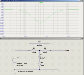
A few minutes tinkering with a mistuned tee filter got me pretty close to your favourite SLO curve. This circuit has very little loss except at the notch frequency, in fact, I had to dial down the virtual input voltage level in LTSpice to mimic the (-4dB) level of your SLO curve.I more or less was trying to mimic the response of my fav settings from a SLO tonestack.
If you make the 68k resistor variable, you can dial the depth of the notch up or down. But this is strictly a mid control, as bass and treble responses are fixed.
I'm attaching both a screen capture, and the LTSpice simulation file (.asc), for your tinkering pleasure.
What do you think?
-Gnobuddy
Attachments
...mimic the response of my fav settings from a SLO tonestack. The values needed to get there seem a bit screwy, but I don't fully understand the James TS anyways....
The James is simple. Everything is 10:1 ratios. Set there, it is "flat" with 20dB loss. Turn the knobs, bass and treb can boost to near unity or cut 20dB on top of the base 20dB loss. It is a beautiful thing in graphs.
Guitarists use more boost than cut. The Fender (most others are copycats) cuts everything and then adds-back bass and treb to taste. The broadband cut is sometimes adjustable and the knob is called "mid".
If you like the SLO tonestack, why not use the SLO tonestack? It has fewer parts than a James. It does not waste half the knob range with cuts the guitarist will rarely want. If you have a "perfect setting", mock it up with pots, find your setting, take the pots out, measure, and use fixed resistors.
Gnobuddy's Tee would also work. It should be checked with a non-infinite load. In typical g-amp topology it will need an input DC-block cap. (Fender tonestack has the incidental property of not needing one, saves a buck.) If you untwist a Fender TS you can see it is also a T network where it counts.
Last edited:
What do you think?
Nice and simple, I'll give it shot!
If you like the SLO tonestack, why not use the SLO tonestack?
Mostly because I don't like how the Treble control affects the mid scoop. On the James, the Bass pot shifts the scoop, but overall there seems to be less interaction between the controls. That, and it's something different and new (for me).
When I first sat down to simulate it, this is what I was expecting, because the active version (popularized by Baxandall, and used in Hi-Fi for decades) is virtually textbook-perfect. A beautiful thing, as you say. I used it a lot in my DIY Hi-Fi days.The James...10:1 ratios...It is a beautiful thing in graphs.
Sadly, the passive James (?) tone control we are discussing here is not very nice at all. IMO, it's more of an ugly mess than a beautiful thing.
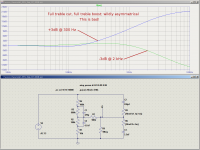
As just one example, take a look at the attached screenshot. Set to full treble boost, the +3 dB corner frequency is 300 Hz. Set to full cut, you would expect the -3 dB corner frequency to be the same 300 Hz.
Instead, you get - wait for it - 2 kHz. 😡 Nearly an order of magnitude higher. 😡
Needless to say, with hugely different corner frequencies, the treble cut curves are nothing like the treble boost curves.
I originally simulated it with a 1M load. The bass end of the response droops a couple of dB, because of the voltage divider formed by the two 150k resistors and the 1M load.Gnobuddy's Tee would also work. It should be checked with a non-infinite load.
So I would suggest running the output straight into the grid of the next valve, and putting a 1M resistor from input of the Tee filter to ground, to make sure that grid is ground-referenced. The 1M resistance at the input will add very little additional loading to whatever previous stage is driving this Tee filter.
-Gnobuddy
Attachments
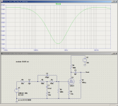
I tinkered a bit with the Tee filter, adding a 40k source impedance to simulate a preceding 12AX7 triode, and adding a simulated 12AX7 triode to the output.
Curiously enough, I got the flattest response (equal bass and treble levels outside the notch region) with a 680k grid bias resistor for the following gain stage.
Screenshot attached.
-Gnobuddy
Curiously enough, I got the flattest response (equal bass and treble levels outside the notch region) with a 680k grid bias resistor for the following gain stage.
Screenshot attached.
-Gnobuddy
Attachments
...treble cut curves are nothing like the treble boost curves....
Except for the special-case of undoing unwise equalization, I'm not sure why they should mirror? Your reasons for doing cut are usually different from your reasons to do boost.
I do agree that the James tends to boost far down in midrange or else has limited effect by 10KHz. But that does give a "Wow!" boost, sells the product.
You are not going to do better with a passive network.
The Bax IS better because it uses Linear tapers and can be true symmetric (pretty graphs), at the cost of integrating a gain-stage into the EQ.
In real life, I was fond of James as a party tool. But have not had one in decades.
I tinkered a bit with the Tee filter, adding a 40k source impedance to simulate a preceding 12AX7 triode, and adding a simulated 12AX7 triode to the output.
Curiously enough, I got the flattest response (equal bass and treble levels outside the notch region) with a 680k grid bias resistor for the following gain stage.
Screenshot attached.
-Gnobuddy
These sims are very helpful, thank you. In a real world application this could be useful for a no frills pre-emphasis eq early in the preamp.
How would the sim look with a LTP as U1 (second gain stage)?
A bit off topic, but since tone stacks are the discussion...
What is the load of the standard fender TS? Measured in circuit the only reading I can get as at lug 1 of the treble pot... but that's just the value in parallel with the gain pot. Or, is that the actual load the previous gain stage sees as "Rp"?
It know it doesn't really matter, just curious.
What is the load of the standard fender TS? Measured in circuit the only reading I can get as at lug 1 of the treble pot... but that's just the value in parallel with the gain pot. Or, is that the actual load the previous gain stage sees as "Rp"?
It know it doesn't really matter, just curious.
For me, it's about controls that are as uniform and predictable as possible. When you are both musician and sound-guy, you lose your musician creative right-brain-dominant mental state if you have to get into the problem-solving left brain dominant state to figure out what the hell those non-linear, non-intuitive tone controls are doing.I'm not sure why they should mirror?
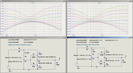
So far, my favourite passive tone control is a heavily tweaked version of the Voight tone control from Merlin Blencowe's preamp design book. Screenshots and .asc file attached.You are not going to do better with a passive network.
The tweaked Voight is not quite as nice as an (active) Baxandall, but is not bad at all. Both pots are logarithmic. There is very little interaction between treble and bass controls, and for the most part, EQ changes quite smoothly and predictably with control rotation.
The flaws are fairly minor: midrange gain does change slightly from full boost to full cut, and control response does tail off a little bit for both bass and treble at full cut.
-Gnobuddy
Attachments
You're very welcome. LTSpice is a wonderful tool when we start thinking about circuits too complex to solve the frequency response curve in your head. 🙂These sims are very helpful, thank you.
For me, the danger is the temptation to sit and simulate twenty different things, instead of heading over to the workbench and actually soldering something together. It is so easy for us to be pulled into synthetic fantasy-land by computers!
I don't think that would change anything. The notch filter pretty much sees the grid bias resistor of the next valve as it's load, whether that valve is part of an LTP or not.How would the sim look with a LTP as U1 (second gain stage)?
-Gnobuddy
Usually the load is (mostly) the volume pot that immediately follows the tone stack. At high volume settings, the grid bias resistor of the next stage is effectively in parallel with the volume pot, so it loads the TS a wee bit as well.What is the load of the standard fender TS?
LND150 (and similar) MOSFETs are cheap, and super-easy to stick on to any valve gain stage as an output buffer. They make cheap and convenient gain stages for active tone controls too, you just have to use a couple of resistors somewhere in front of them to cut down the maximum signal strength so the MOSFET itself never enters clipping. This is an ace we have up our sleeves that simply didn't exist in Leo Fender's time.
-Gnobuddy
The Voight is a clever thing. What I wonder about is the great different in slopes, boost or cut. Slope often is more obvious than nominal corner frequency. But it sure is simple. And seems to lack the small wonkiness the James can get through the middle.
For small cuts and boosts, the Voight is almost perfectly symmetrical - astonishingly so! See attached files.What I wonder about is the great different in slopes, boost or cut.
You're right, it's not as perfect at full boost and cut. But it's still much closer to perfect than the usual Fender TMB circuit. In use, my fingers don't notice any issues with the Voight, and the controls feel smooth and predictable, probably in part because I rarely find myself using those extreme tone control settings.
For this simulation, I picked the central value of "k" (pot position) carefully to showcase the flat-response setting, which is again astonishingly good - virtually perfectly flat. Other than that, the simulation isn't tweaked in any way - just small, equal value steps in pot rotation on both sides of the central, flat-response setting.
-Gnobuddy
Attachments

- Status
- Not open for further replies.
- Home
- Live Sound
- Instruments and Amps
- please help me to understand filters