Hi folks.
I am working on a guitar pre-amp as a pedal. found milions of schematics and layouts and finally picked up one to build. my choice is "Green Citrus" because it sounds very like "Holy Mountain" by "Midnight Amplification" my project is almost done, pcb is here and all elements are in place. when i tested this preamp i have found that 'Treble' knob doesn't "do" much, the difference is barely noticed by ear.
the questions are :
1. what kind of filters are being used here ?
2. how can i affect those filters ? (what happend if increased and decreased)
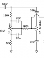
the piece of schematic responsible for the tone is attached to this post.
Thank You in advance for help
I am working on a guitar pre-amp as a pedal. found milions of schematics and layouts and finally picked up one to build. my choice is "Green Citrus" because it sounds very like "Holy Mountain" by "Midnight Amplification" my project is almost done, pcb is here and all elements are in place. when i tested this preamp i have found that 'Treble' knob doesn't "do" much, the difference is barely noticed by ear.
the questions are :
1. what kind of filters are being used here ?
2. how can i affect those filters ? (what happend if increased and decreased)
the piece of schematic responsible for the tone is attached to this post.
Thank You in advance for help
Attachments
Last edited by a moderator:
That is what is called a 'passive' tone control network. These have quite a high attenuation (it cuts down the signal) and they also have more limited boost and cut compared to the more usual 'active' type that would need either a transistor or opamp to add gain.
Its very important that you feed the circuit from a low impedance source (less than around 1k) and that you take the output to a high impedance (1meg or more). Not doing that will affect the way the circuit works.
Its very important that you feed the circuit from a low impedance source (less than around 1k) and that you take the output to a high impedance (1meg or more). Not doing that will affect the way the circuit works.
thank you for your reply on this
that tone control network is located between transistors , so it could be ok with gain i hope:
http://guitar-fx-layouts.42897.x6.nabble.com/file/n9872/green-citrus2-1.gif
is it still possible to change the values of some components to get better 'Treble action' ?
(i am asking "still possible" because i got PCB already here)
The transistors provide the correct operation conditions I mentioned (low Z to drive it and high Z that it feeds into) but it is still what we call a 'passive' tone control. An active tone control incorporates the filters within a feedback network around the transistor or opamp.
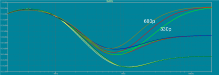
So you want to change the frequencies. In a way its trial and error for you to get the effect that you want. Increasing the 330pF cap (say to 680pF or 1000pF) will make the treble control work lower down the frequency range... so more noticeable. Increasing the 2n2 that goes in series with the treble control will cut more treble out as you turn the treble down. Experiment and see what suits you best.
http://makearadio.com/tech/tone.htm
1. what kind of filters are being used here ?
- its a "James" tonestack or "passiv Baxandall"
2. how can i affect those filters ? (what happend if increased and decreased)
- for more Treble increased the 330p Cap. (see attachment)
just a little helper for question like this...
tone stack calculator
TSC
good luck
- its a "James" tonestack or "passiv Baxandall"
2. how can i affect those filters ? (what happend if increased and decreased)
- for more Treble increased the 330p Cap. (see attachment)
just a little helper for question like this...
tone stack calculator
TSC
good luck
Attachments
hi again
i think i got this working finally. the reason i could not hear the EQ working was the transistors bias (of course).
i got it all wrong. i still cannot set the bias as it should be, but i'm getting closer 🙂
i think we can consider this topic as closed.
You helped me understand the how these filters work.
thank you
Each trim pot will adjust the voltage on the Drain of the FET it connects to. It looks to me like the design could be extremely critical on the type of FET used... and I assume there are specific instructions for setting the trim pots.
IMO, those 100k pots are an order of magnitude too big. A major screw-up by the designer.It looks to me like the design could be extremely critical on the type of FET used...
With a fairly typical 1V - 2V DC at the source, quiescent drain currents will be in the ballpark of 0.5 mA - 1 mA. With a 9V supply, the drain loads should drop very roughly 3 - 5 volts, which means they will end up with resistances roughly between 10k and 3k. Trying to set a 100k trimpot to 3k is a ridiculous and futile exercise.
I suggest using 10k or 22k trimpots for all four drain resistors, rather than 100k ones. That should make it a lot easier to adjust the bias properly.
-Gnobuddy
True enough.That plan should have heaps of treble boost/cut.
When it comes to bass rather than treble, though, about half the bass boost/cut is only available at frequencies below 80 Hz. A six-string guitar in standard tuning produces no frequencies below 80 Hz. 🙄
-Gnobuddy
FULLY agree 🙂IMO, those 100k pots are an order of magnitude too big. A major screw-up by the designer.
With a fairly typical 1V - 2V DC at the source, quiescent drain currents will be in the ballpark of 0.5 mA - 1 mA. With a 9V supply, the drain loads should drop very roughly 3 - 5 volts, which means they will end up with resistances roughly between 10k and 3k. Trying to set a 100k trimpot to 3k is a ridiculous and futile exercise.
I suggest using 10k or 22k trimpots for all four drain resistors, rather than 100k ones. That should make it a lot easier to adjust the bias properly.
-Gnobuddy
I am sick of those cheesy "designs".
In fact, there is no *design* involved, at all.
All they do is pick some classic design, say a Fender gain stage: one 12AX7 triode, 1k5 cathode, 100k plate, 260V power rail, and "convert it to FET" ... which can be done, of course ... the proper way: you have to *design* a Fet gain stage, bias it, feed it proper voltage (say, 25V or so), etc.
So you have to determine stage current, bias, source and drain resistors, etc.
Cheesy "designers" just copy Fender (or Ampeg/Marshall/Vox/whatever) **tube** designs, place a Fet (any FET 😱 ) instead of the triode, and then same resistor values as in the tube amp ... WTF????? 😱
Of course idle current, biasing, gain, is all over the place, so to at least have drain voltage around 4.5V they adjust the 100 k trimmer to any needed value, sometimes 1/20th or less of the nominal 100k 🙄
When I ask some why did they use thos resistor values, how they calculated them, they answer "hey, those are the original schematic values!!!!" .
Fine with me .... if you also use original schematic 12AX7 and 250V rails, otherwise ......
But they think those are somehow "magic numbers" which must be respected to death, even if absolutely wrong.
Worst thing is they "think" they are using "magic number" 100k "plate resistors" 🙄
Well, they are NOT, trimmers are "magic 100k" ... end to end .... but are never ever set to such a high value, actually those you mentioned.
But "designers" are oblivious to that.
When I ask somebody "why did you choose that Fet? .... what´s its Vp? ..... what Idss? ...." I get deer in the headlights looks. 🙄
Absolutely NO CLUE.
You are absolutely right. I found a couple of threads on a different forum about the circuit being discussed in this thread, and the general concept of just replacing triode valves by JFETs. It soon became very obvious that the "designers" had no idea what they're doing.In fact, there is no *design* involved, at all.
For example, there was a discussion about interstage coupling capacitors. The conclusion was that they should be 0.068uF, because the original (valve) guitar amp used that value. Nobody mentioned that the original 12AX7 stages have about 40k output impedance, while the JFET substitute has ten times less output resistance. Nobody mentioned it is not the "C" value which is magic, but the RC product. With ten times less R, how can the same C value be ideal?
(In this particular case, the "designers" got lucky, because the gain stages were feeding 1M loads, which swamp out the much smaller difference in resistance between half-12AX7 and J201 JFET. Sometimes ignorance really is bliss!)
-Gnobuddy
I have the feeling Tone Stack Calculator presents a rather rosy picture of the passive Baxandall tone control circuit. TSC shows only the full boost and full cut curves, which can hide much of the ugly behaviour of a circuit. And the passive Baxandall tone control seems to be quite an ugly circuit!
(The active Baxandall, by contrast, is extremely well behaved, which is why it became the standard for Hi-Fi for many decades.)
A well behaved tone control should have these qualities:
Some notes about the attached images:
-Gnobuddy
(The active Baxandall, by contrast, is extremely well behaved, which is why it became the standard for Hi-Fi for many decades.)
A well behaved tone control should have these qualities:
- Cut and boost curves are symmetrical.
- Equal changes in pot rotation produce roughly equal changes in cut and boost.
- There is sufficient control range within the frequencies of interest.
- There is a central flat-frequency setting.
- The bass and treble pots do not interact with each other.
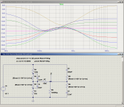
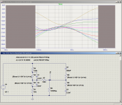
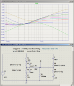
Some notes about the attached images:
- The equations next to the potentiometers are to simulate the normal "10% audio taper" pots, i.e., logarithmic pots with 10% of full resistance at the half-way setting. I deduced these equations myself.
- The second image shows what happens in the frequency range relevant to electric guitars, i.e., from 80 Hz to maybe 5 - 6 kHz. The weak and wildly non-linear bass control response speaks for itself.
- The full treble cut curve in my simulation differs from the same curve as posted by PRR using Tone Stack Calculator, because at the zero position, the pot equations I used still have 1% of total pot resistance, rather than exactly zero. 1% change in resistance should not produce enormous changes in frequency response in any well-behaved tone control circuit...
- The other three full cut and boost curves match the ones from Tone Stack Calculator.
-Gnobuddy
Attachments
...Tone Stack Calculator .. shows only the full boost and full cut curves...
...the passive Baxandall tone control seems to be quite an ugly circuit!...
Baxandall's name should not be applied to the passive network. (If you must use a name, James wrote the paper usually cited.)
TSC *can* show the complete response for any sane number of knob setting.
Attachments
Okay.Baxandall's name should not be applied to the passive network.
Excellent, that's very useful when it comes to tone controls.TSC *can* show the complete response for any sane number of knob setting.
-Gnobuddy
I should have noted: TSC will let you see the curves *interactively*. You can discover interacting things that are not shown by a SPICE sweep, even a nested sweep.
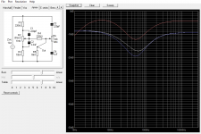
In case anyone was wondering - here is the same tone control, except linear pots have been used (instead of 10% audio taper log pots.) You can see that the equations beside the pots have changed accordingly. Frequency responses have been plotted from 80 Hz to 6 kHz, which encompasses the full range for electric guitar.
IMO the frequency responses still look like a dog's breakfast, being uneven, asymmetric, unequally spaced, and lacking an easily located central flat response.
Perhaps there is some magic set of component values that makes this circuit behave well, but if so, I have failed to find them. I've simulated several variants from various sources attempting to do so, without any luck.
So far, the best-behaved passive tone control circuit I've found is a Voight circuit I tweaked considerably. And if one goes for familiarity rather than good behaviour, the infamous Fender/Marshall/Vox "tone stack" will probably win by a landslide, simply because it is so widely used.
For DIY guitar amps and FX pedals, there seems to be no reason why one shouldn't use the (active) Baxandall circuit, which is extremely well behaved and easy to use to dial-in the sound you want. All you have to do is use a pair of resistors in the circuit to limit the maximum signal strength going into the tone control input, to keep the tone control itself from ever clipping. (Never clip an active tone control circuit, as it will both distort harshly, and stop behaving like a tone control circuit during clipping.)
-Gnobuddy
Attachments
I tinkered with TSC some years ago, before I had learned how to use LTSpice. Those sliders seemed useful at first sight, but I found that having a static snapshot of several frequency response curves was a much better visualization tool, at least for my brain. So for me, TSC is a distant second place in terms of being able to see what the circuit does.I should have noted: TSC will let you see the curves *interactively*. You can discover interacting things that are not shown by a SPICE sweep, even a nested sweep.
But to each their own. I've been around enough smart technical people to know that we don't all see or process things the same way. The more good free tools are out there, the better for all of us.
-Gnobuddy
Perhaps there is some magic set of component values that makes this circuit behave well, but if so, I have failed to find them. I've simulated several variants from various sources attempting to do so, without any luck.
After many moons messing with it, I finally came about values that "look good". Hopefully sooner than later I'll have the chance to test it out.
I more or less was trying to mimic the response of my fav settings from a SLO tonestack. The values needed to get there seem a bit screwy, but I don't fully understand the James TS anyways.
The red curve is the Soldano set to T6 / M4 / B5.
The James TS settings were 7 for both T/B. I guess I should have did a full sweep 😎
White curve is James with C2 set to 2.2n. Increasing C2 to 3.2 (approx a switchable parallel 1n) decreases low mid response a decent amount, represented by the blue curve. BTW, this is assuming being fed from a CF.
It's rather lossy, but I couldn't smooth out the response unless I used large resistors at R1 and R4. I don't particular care unless it actually sounds lossy.
EDIT: It just occured to me that I should scaled the values to suit the source Z. I'mma dumby... 😕
Attachments
Last edited:
- Status
- Not open for further replies.
- Home
- Live Sound
- Instruments and Amps
- please help me to understand filters