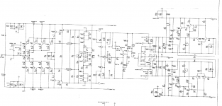
Udklip: 3 kaskoded audio kaskoded differensial stages.
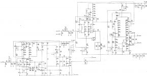
Udklip1 : negative on top (upsde down AND reading normaly left TO right, here right to left.
LEFT TO RIGHT: Output stage AND regulated power supply
Udklip1 : negative on top (upsde down AND reading normaly left TO right, here right to left.
LEFT TO RIGHT: Output stage AND regulated power supply

Thank you so much, very kind of you! 🙂Udklip: 3 kaskoded audio kaskoded differensial stages.
Udklip1 : negative on top (upsde down AND reading normaly left TO right, here right to left.
LEFT TO RIGHT: Output stage AND regulated power supply
Thank you, this was my next question but according to the list is there included an ML27.5, but it should not surprise me if this mess should contain errors with the names also. 🙂You will get a more meaningful discussion if you change the thread name to include ML23.5. One of the greatest amps of the past.
Thank you, you are amazing!Here is a detailed explanation of how the 27.5 works
I know it is a class A - A/B and suck a fair amount of power, I am wondering what would happen if I "remove" the transformer itself, but keep the rest and then connect an SMPS in the transformer's place? I mean, keep it all but avoid the big heavy and hungry transformer?
Not a big fan of SMPS use in audio, so perhaps someone else will chime in here. As long as you find a unit to cover the VA requirements (not trivial), electrically everything will be fine. Fwiw ML's class D amps still use a conventional linear PS.
To my luck do we have one of the best SMPS designers in the world on YouTube! Maybe if one could try to persuade him to make a series about how to get rid of the SMPS artifacts! 🙂Not a big fan of SMPS use in audio, so perhaps someone else will chime in here. As long as you find a unit to cover the VA requirements (not trivial), electrically everything will be fine. Fwiw ML's class D amps still use a conventional linear PS.
The thing about SMPS, they are sold without a case & filters. The pro SMPS amps I own, they put the SMPS in a steel box and have filters on both AC input and DC output. This keeps the RF howl from interfering with the amplifier parts. The steel box has to be designed to fit the air flow design of the existing case. All three of the SMPS amps I've owned used a fan.
Oh, in that way. Couldn't I "just" build a separate case to be placed away from the main amplifier?
By the way, the upside down schematic should be both an Output stage AND regulated power supply, What side is the PSU? Sorry but I have a hard time identify it, I assume the two parts are only connected with that one single track and a GND?
By the way, the upside down schematic should be both an Output stage AND regulated power supply, What side is the PSU? Sorry but I have a hard time identify it, I assume the two parts are only connected with that one single track and a GND?
- Home
- Amplifiers
- Solid State
- Please help me to identify the main function of these two amp schematic?