Hi everybody,
I just finished building SE 300b Legacy by Thorsten. Something strange is happening or at list I have never seen anything like this before.
When the amp is first turned on the voltage on the filament of the 300b is 5V. After a few seconds the voltage start to rise up to 68V. That is how it should be. Than it stays at that voltage for about 2-3 seconds and start to fall down to 0V. This fall in the voltage is accomanied by motorboating sound from the speaker.
in meantime the 5V regulator gets very very hot. I measure all the volages in the cct and here is what they are: HT 418V, reference voltage in the HT regulator cct 81V, the voltage at the plate of SV83 it measures 303V and it should be 270V, the voltage at the cathode of the same valve is 5.1V and it should be 5.5V, the voltage at the junction of R1,R2,C1,R4, is 162V and should be 160V. The voltage at the top of C7,C8 just after the rectifiers is lower then it should be at 455V.
The testing of 5V power supply without load show no sign of any problem. As a matter of fact I installed second 5V supply and had the same problem. I also check the HT regulator without load and I was able to ajust HT without problems.
I check all the wiring so meny times and for the life in me I can't find what I did wrong.
Thorsten and everybody else, I would be very thankfull if you can get involved and help me solve this problem. Thank you.
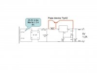
Here is the link to schematic
http://www.fortunecity.com/rivendell/xentar/1179/projects/legacy/Legacy.html
http://www.fortunecity.com/rivendell/xentar/1179/projects/legacy/Legacy.html
hi, if the voltage at the cathode of the output tube is falling to zero, then something is dragging it down,
As the, cathode resistor and bypass resistor pair, and the voltage regulator seems to be the only thing in the circuit at that point, then there has to be something wrong in that area.
try disconnecting the HT to the top of the transformer, what does the voltage regulator do then?
As the voltage rises to the proper value on the cathode resistor, is there something wrong with the cap? what rating is it? is it breaking down. disconnect the capacitor to see if that stabilises the dc voltages, it will have no effect at dc levels.
Also, look for sneaky earth connections in the heater regulator, from what I see the heater supply should be floating, therefore each leg should have a high impedance to earth.
It also, check the capacitor on the grid, is there by any chance a leak there, you may have a faulty cap there and dc is getting through to the grid, however, as you note, the voltage on the cathode dissapears, so it is unlikely that that will have any effect.
Have a good sniff around the regulator and the cathode connections to the output valve and you will probably find your problems there.
Motorboating for what its worth is usually caused by poor decoupling between stages on the HT line.
hope that this is of some help.
Kind regards
BIll
Hi,
Have you checked to make sure your filament regulator has adequate heatsinking? Are you using thermal grease/mica or silpad?
What you describe sounds suspiciously like the filament voltage dropping or going away - the loss of cathode voltage would indicate the loss of filament emission. Check the filament voltage right at the socket pins (not to ground) and see what happens.
Removing the HT (high voltage) from the output transformer will also remove the cathode bias so won't tell you much. You can still check filament voltage under these conditions.
I don't know what regulator comes with the kit, but small monolithics like the 7805/LM317 are only good for 1.5A and only with a good heatsink. 300B use anywhere from 1.2A to 2A depending on vendor. JJ uses about 1.5A as a reference point. You can bypass a percentage of the load current around the regulator without significant degradation of noise performance and regulation with a shunt resistor. In this case I would recommend about 10 ohms in parallel with the regulator input/output terminals. An alternative would be to use an LT1085 regulator it can handle up to 3A with proper heatsinking.
You did not indicate what the line voltage was when you made the other voltage measurements, in any case none of them sound badly out of line. Tolerances of 10% in tube designs is not uncommon, but without knowing the line voltage it is impossible to know whether the voltages are in the correct range compensating for line voltage variations. (Regulated supplies generally have much tighter tolerances and should be within a couple of % of specified values.)
Variations in tube parameters like transconductance will result in slightly different operating points for all self biased tube amplifier circuits.
Kevin
Thank you guys for your response. You guys gave me a lot of clues and here is what I faind out so fahr:
I did all the checking you guys sugested but I could not find anything wrong with cct or with any of the parts in the cct. So, after sugestion to pay close attention to heat sink I went on a Linear Technology WEB site and actualy faind out that LT1085 has built in termal protection cct. I replaced the heat sink and that coused delay in fall of the cathode voltage. At a moment I don't have biger heat sink to try it again. Insted I bypassed the regulator. Well the amp works but it is not anymore the universal amp since there is no more LT adjustement. However, there is one thing that wories me. The voltage on a plate of SV83 is still 21V higher than in the schematic. It should be 270V and I measured 291V. Since I'm new to a valve cct-s I don't know if I should wory about this descrepency in voltage. So your opinion will be again appreciated.
The line voltage is 220V measured at the primary of the trafo.
Again thank you so much for the help.
Yes, most monolithic regulators use thermal protection to prevent damage due to excessive heating in the die. Did you use thermal grease on the tab of the 1085 before you installed the heatsink? Note that you can add a parallel resistor to reduce the load on the regulator as I noted in an earlier post. (10 ohms would probably do it.) Do you know the voltage at the input to the regulator? It does not need to be more than a couple of volts higher than the output voltage of the 1085 as it has a fairly low drop out voltage, anything more and you are unnecessarily asking the regulator to dissipate power.
The 21V higher plate voltage is probably an indication that the SV83 is drawing a little less plate current than typical, but it is still within about 10% of nominal, you might want to check with the manufacturer of your kit if possible.
Kevin
The 21V higher plate voltage is probably an indication that the SV83 is drawing a little less plate current than typical, but it is still within about 10% of nominal, you might want to check with the manufacturer of your kit if possible.
Kevin
Hi Kevin,
Yes I use heatsink grease. I'll try paralelling the regulator. Will 25W resistor be suficient for the task? The voltage at the input pin of the regulator is a bit high 13.8V. Reason is that I have this trafo with secondary windings of 6.6V so I use two in series. I can bring voltage down to mayby 8V as I like to have room to vary voltage up to 7.5V so I can use diferent output valves. Will 5 Ohm 10W do the job? Thank you.
Yes I use heatsink grease. I'll try paralelling the regulator. Will 25W resistor be suficient for the task? The voltage at the input pin of the regulator is a bit high 13.8V. Reason is that I have this trafo with secondary windings of 6.6V so I use two in series. I can bring voltage down to mayby 8V as I like to have room to vary voltage up to 7.5V so I can use diferent output valves. Will 5 Ohm 10W do the job? Thank you.
MlinarS said:Here is the link to schematic
[/URL]
Kevin, the running away can be solved with an extra transistor and a resistor.
This works OK and the voltage still can be regulated. I have used this even for class-A output stages.
Remark: The 2A AC secondary to me is too week for a 1,2 A DC current.
Success.
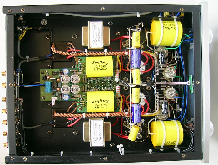
Attachments
Hello Triode_Al,
Thanks for the response. Actualy secondary on my trafo is rated at 3A AC. I can see from your drowing that the transistor is PNP. What kind transistor is this (power, etc.)? This is interesting aproach. To update you on what I did last I lower the voltage on input of the regulator to 8V and regulator is runing cool as a cucumber. No problem at all. I don't think I'll need to parallel the regulator with anything. Although the resistor is runing hot but that is to be expected. Thanks.
Thanks for the response. Actualy secondary on my trafo is rated at 3A AC. I can see from your drowing that the transistor is PNP. What kind transistor is this (power, etc.)? This is interesting aproach. To update you on what I did last I lower the voltage on input of the regulator to 8V and regulator is runing cool as a cucumber. No problem at all. I don't think I'll need to parallel the regulator with anything. Although the resistor is runing hot but that is to be expected. Thanks.
Hard to predict the future is, (Yoda) and so hard is to tell you somenting helpful, but just a hint, and take it "as is", check for oscillation of the regulators, those damn things are prone to oscillate crazyly if not bypassed by a ceramic cap from the input and output pin to common or a nearby ground.
When it occured to me an LM338 was oscillating (and trasmitting) at about 120Mhz and everithing nearby was behaving like a mad cow.
Cheers
Larry.
When it occured to me an LM338 was oscillating (and trasmitting) at about 120Mhz and everithing nearby was behaving like a mad cow.
Cheers
Larry.
Actually you should address your comments to Mlinar, and you don't even need the transistor to do this, just a moderate value power resistor across the regulator will do it, to work properly of course that assumes a relatively constant load current. I have done it repeatedly in commercial designs where cost is a factor.
In this particular case I recommend 10 ohms/10W in parallel or alternately I would recommend reconfiguring the secondaries in parallel for roughly 8V raw dc and regulate that down to 5V for the 300B. Currently the 1085 is dissipating nearly 10W. Note that you could use a dpdt toggle to allow series or parallel connection of the secondaries for use with 5V tubes and 7.5V tubes with an additional adjustment to the regulator voltage setting resistors.
Kevin
That's cool!kevinkr said:I recommend 10 ohms/10W in parallel
Kevin
To MlinarS then
 : the 0,47 ohm is suspect to me as well: take a 5 amp peak load current during some degrees of the sinus -- that takes the voltage down considerably. The 7,5 V would already never give you more that 8V raw and with this you shuold be lucky to have 7V. So i would take that out for a second start at the problem.
You guys have been very helpful. Unfortunately last night my DVM died on me. So this project will have to wait until I get new DVM.
Thank you so much everybody.
Thank you so much everybody.
Problem with PrimaLuna prologue 3 preamplifier
I have measured a problem with left channel output - strange response and more distortion. Switching tubes does not change anything. one cap near line out seem to be blown...
What could cause this kind of response change?
I have measured a problem with left channel output - strange response and more distortion. Switching tubes does not change anything. one cap near line out seem to be blown...
What could cause this kind of response change?
Attachments
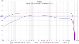
Problem solved! My friend changed those C209 and also C109 electrolytes an the amp measured well. At home -same problem. After trying different inputs, measuring my dad output, changing cables etc. I took off the RCA-cable from Line Out2 R channel - it goes to subwoofer amplifier Hypex DS2.0 and it was just that! These line-outs are parallel (impedance 2,8 kOhm) and the input impedance of Hypex is 10 kOhm. http://www.hypex.nl/docs/DS20_manual.pdf
- Status
- Not open for further replies.
- Home
- Amplifiers
- Tubes / Valves
- Please help me solve the problem