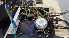
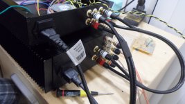
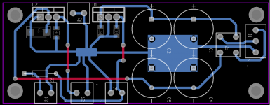
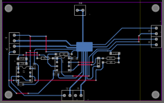
I'm having ground loop issues when connecting my active crossover to my amp. When my amp is hooked up to my speakers without any input (rca's unconnected), the speakers are completely silent. My amp's chassis and power supply ground is connected to earth ground.
However, after connecting my active crossover (pictured) to my amp, I get ground loop hum. If I leave the earth ground unconnected (the green wire in the first pic) the hum is gone. Just to summarize:
Amp (earthed) + Active Crossover (earthed) = hum
Amp (earthed) + Active Crossover (unearthed) = silent.
It doesn't matter which ground I connect the earth ground in my active crossover (power supply ground, speaker ground, etc), the hum happens when its connected.
I've attached pics of my setup and my layout for both the active crossover power supply and the main board. If you'd like anymore pics or tests for me to do let me know.
Attachments
You did mean to say that your amplifier's signal ground is connected to chassis (mains protective) ground?
Is the signal ground of your active filter(s) also connected to chassis and protective ground again?
If so, the answer is there - the signal ground of the crossover unit should not be reconnected to protective
ground via another mains loop.
There are safety issues with floating the signal ground above chassis ground but commercial signal processing
devices are typically isolated or otherwise known as "double insulated" which avoids this chain of secondary
grounding problems. For a basic overview -
Earthing (Grounding) Your Hi-Fi - Tricks and Techniques
You did mean to say that your amplifier's signal ground is connected to chassis (mains protective) ground?
Yes, but not directly. In my amp, the chassis ground is connected to the power supply ground, and the power supply ground is connected to the signal ground (but not at the exact same point).
Is the signal ground of your active filter(s) also connected to chassis and protective ground again?
If so, the answer is there - the signal ground of the crossover unit should not be reconnected to protective
ground via another mains loop.
There are safety issues with floating the signal ground above chassis ground but commercial signal processing
devices are typically isolated or otherwise known as "double insulated" which avoids this chain of secondary
grounding problems. For a basic overview -
Earthing (Grounding) Your Hi-Fi - Tricks and Techniques
Yes, my active crossover is connected the same way, earth/chassis ground eventually connects to signal ground.
So are you saying is that by design, active filters and processors are *not* suppose to be connected to chassis ground?
Just connect the signal ground to the chassis using 10ohm resistor, instead of direct connection, in the crossover. This is easy test. If it will be successful, than You can use 10ohm/5W resistor, parallel with 100nF ceramic capacitor.
Sajti
Sajti
The point is not whether they should be grounded but where. If you connect signal ground to loop after loop of chassis/mains leads used throughout your signal chain, you have created a series of ground loops, right? Take a little time reading the linked article and references to see the bigger picture we all have to deal with in getting into building processors, preamps etc. as opposed to amplifiers which we continuously post on this SS amplifier forum and most of us soon get the hang of. In a typical line level device, the chassis and transformer primary are mains connected but the secondary and PSU is isolated from chassis ground so the output and thus the signal circuitry floats. This is not safe by modern standards and requires a safety "ground lift" device to establish a safe potential for exposed connectors.
As an illustration of what's out there, I bought an Ebay preassembled preamp for a client in a hurry and he was extremely happy but when I checked, only a floating power supply and outputs. It will be safe enough upon connection with good cables to an amplifier but on its own...?
Think of a situation where your active filter is powered by an AC wall-wart or an isolated DC bench power supply. No protective ground, no mains issues and plenty big enough to run several filters and more. Would you still have a ground loop? Nope, and it most likely will kill 95% of the hum too. I build basic preamps this way because it is cheap, relatively safe to use and very low noise but others like to do things more traditionally and correctly with self-contained supplies and all the extra features. Fine, but you need to be aware of the grounding issues of doing it that way. In the past, some amps were fitted with a number of line sockets which kept mains ground in series rather than allowing long loops with other mains outlets, for instance. Others with 2 pin US style line sockets were not particularly safe but seldom had hum issues because there was simply no common protective ground to cause problems.
The grounding issue and procedures can be quite different and vary over the period since the US, along with other countries, changed to grounded mains systems but there is plenty of gear still with 2 wire zip cord. In this country at least, DIYs have always been required to fit protective earth to equipment with metal surfaces or connections that can be touched. Not necessarily for the manufacturers though, as they have to conform to insulation test requirements.
I should add that correctly routed protective earthed systems are lower noise than ungrounded ones but, as others say, it's not so straightforward implementing them in all designs. Formal explanations in Douglas Self's, Bob Cordell's or Randy Slone's and others designers' books can be very good references that include these more complex issues.
Check this subject out in the analog line-level forum too.
Last edited:
From what I read in these forums, this issue is a perennial gotcha which never gets a satisfactory answer. Some people dogmatically stick to the line that all exposed metalwork in a non-commercial device must be connected with a hefty safety ground to earth, but this must always lead to ground loops when connecting an earthed PC, for example, to an amp..?
Some people suggest that leaving the earth off is 'probably' OK, or that you can rely on signal cables for earth continuity. Some people suggest the home made 'earth lift device' e.g. a hefty bridge rectifier with parallel resistor. None of these solutions fills me with confidence.
Could an expert tell us:
(a) Is it possible for a home constructor to build a mains-powered device that doesn't need an earth? Would this require use of an approved transformer (it doesn't guarantee the user knows what he is doing with it), or even a completely encapsulated approved power transformer with fitted mains socket and switch, and AC out? (If these aren't available, they should be.)
(b) Is it possible to buy an approved 'earth lift device'?
Either of these solutions would, presumably, solve the problem at a stroke.
The question should be:
Can I be trained to design and build and test and guarantee the ClassII equipment?
Your life and that of any family and/or visitors depends on the quality of that training and testing.
Can I be trained to design and build and test and guarantee the ClassII equipment?
Your life and that of any family and/or visitors depends on the quality of that training and testing.
Coppertop,
have you read my report of the test I carried out on the Disconnecting Network?
Hi Andrew. No I haven't - do you have a link?
Thanks.
Do we know which transformers are suitable for 'Class II' and which aren't? All we need to know is that the secondary cannot become live. We can earth the enclosure as long as we keep the connectors isolated, and ensure that even detached mains wires cannot physically touch anything after the transformer. I could live with this arrangement.
As an example, would this transformer be suitably approved?
MCTA250/40 - MULTICOMP - TRANSFORMER, 250VA, 2 X 40V | Farnell United Kingdom
It says in the data sheet
All we need for peace of mind is to know is whether the primary->secondary insulation is approved, but the words 'Class II' or even 'double insulated' with respect to this, are very hard to find anywhere.
As an example, would this transformer be suitably approved?
MCTA250/40 - MULTICOMP - TRANSFORMER, 250VA, 2 X 40V | Farnell United Kingdom
It says in the data sheet
Termination:
All leads tri-rated UL1015 style cable rated 600 V / 105°C VW-1
Primary leads double insulated with PVC sleeving for a minimum of 20 mm
Lead lengths ±5 mm approximate all leads ends tinned to 6 mm
Pri / Seconds leads Oº
Standards:
Designed and manufactured in accordance with:
EN60742 (Non short circuit proof),EN60065 (IEC65), EN60950
UL recognised to UL1411, 2601-1 and UL1950 under family approval file E115159
All we need for peace of mind is to know is whether the primary->secondary insulation is approved, but the words 'Class II' or even 'double insulated' with respect to this, are very hard to find anywhere.
Coppertop,
ask your house and contents insurance company if they will insure you against the risks of your version of ClassII equipment becoming faulty and killing someone?
ask your house and contents insurance company if they will insure you against the risks of your version of ClassII equipment becoming faulty and killing someone?
Coppertop,
ask your house and contents insurance company if they will insure you against the risks of your version of ClassII equipment becoming faulty and killing someone?
As I suggested in my first post earlier, the dogmatic "All exposed metalwork must be earthed" line is easy to say, but doesn't actually offer a solution. If the home constructor is going to build an amplifier and use it with an earthed computer, say, is there an approved way of doing it that doesn't give rise to ground loops?
In the absence of anyone telling them how to do it properly, they're going to come up with their own potentially risky solutions.
You know about this stuff. Just tell us how to do it!! 🙂
... Does anybody have any suggestions for my setup/layout/etc? So far the discussion has centered around the theoretical, but is the only solution to not use the earth ground in my active crossover?
Maybe I'm just lucky but when my system was tri-amped, the preamp, the crossover and all three stereo power amps had the line ground connected directly to the chassis, all circuit grounds connected to the chassis and there was no hum problem. The trick is where those connections should be made.
There should never be current flowing in shields, one of which is the chassis. I connect mains ground to the chassis right where the module is, or the cord comes in. Everything else connects to a master ground point, which is usually located at the power supply, and that point also connects to the chassis at a single point close to the power supply. Most RCAs have ground wires that also run to the PS master ground, though my power amps usually mount the RCAs right to the chassis. Finally, everything plugs into a power strip, never into widely separated outlets.
Probably not to the best theory, but it works without fancy ground breaks using resistors or diodes.
- Status
- Not open for further replies.
- Home
- Amplifiers
- Solid State
- Please help me solve my ground loop issues - Pics and layout attached.


