BITTE HELFEN SIE MIR! Mark Levinson ML 23.5
Mir ist echt ein Scheiße passiert!
Ich habe meinen Mark Levinson ML 23.5 vor 1,5 Jahren gewartet und wollte nun den Ruhestrom überprüfen! LEIDER ist beim Messen ein Unfall passiert!
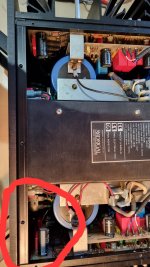
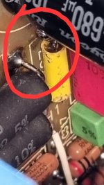
Irgendwie habe ich mit der Messspitze des Multimeters einen Kurzschluss zwischen dem Leistungswiderstand und dem kleinen gelben 10nF Kondensator verursacht! (siehe Foto)
Er zerstörte den Sockel des gelben Kondensators und meine Messspitze komplett. Laut Messung ist der Kondensator in Ordnung. Und eine 8A-Sicherung war auch kaputt!
Nachdem ich die Platine wieder gereinigt, den Sockel des Kondensators ausgetauscht und die Sicherung ausgetauscht hatte, versuchte ich zum ersten Mal die Endstufe wieder einzuschalten!
Der Schalter beginnt zu leuchten und ich dachte, du hast Glück gehabt. LEIDER FÄNGT ES IM VORDEREN BEREICH AN ZU RAUCHEN!
Natürlich habe ich es sofort wieder ausgeschaltet.
BITTE HELFEN SIE MIR!!
Vielen Dank!
Andreas
Mir ist echt ein Scheiße passiert!
Ich habe meinen Mark Levinson ML 23.5 vor 1,5 Jahren gewartet und wollte nun den Ruhestrom überprüfen! LEIDER ist beim Messen ein Unfall passiert!
Irgendwie habe ich mit der Messspitze des Multimeters einen Kurzschluss zwischen dem Leistungswiderstand und dem kleinen gelben 10nF Kondensator verursacht! (siehe Foto)
Er zerstörte den Sockel des gelben Kondensators und meine Messspitze komplett. Laut Messung ist der Kondensator in Ordnung. Und eine 8A-Sicherung war auch kaputt!
Nachdem ich die Platine wieder gereinigt, den Sockel des Kondensators ausgetauscht und die Sicherung ausgetauscht hatte, versuchte ich zum ersten Mal die Endstufe wieder einzuschalten!
Der Schalter beginnt zu leuchten und ich dachte, du hast Glück gehabt. LEIDER FÄNGT ES IM VORDEREN BEREICH AN ZU RAUCHEN!
Natürlich habe ich es sofort wieder ausgeschaltet.
BITTE HELFEN SIE MIR!!
Vielen Dank!
Andreas
Attachments


PLEASE HELP! Mark Levinson ML 23.5
Real **** happened to me!
I serviced my Mark Levinson ML 23.5 1.5 years ago and now I wanted to check the quiescent current! UNFORTUNATELY an accident happened while measuring!
I somehow caused a short circuit between the power resistor and the small yellow 10nF capacitor with the measuring tip of the multimeter! (see photo)
It completely destroyed the base of the yellow capacitor and my measuring tip. According to the measurement, the capacitor is OK. And an 8A fuse was also broken!
After cleaning the circuit board again, replacing the base of the capacitor and replacing the fuse, I tried turning the power amplifier on again for the first time!
The switch starts to light up and I thought you got lucky. UNFORTUNATELY IT STARTS TO SMOKE IN THE FRONT AREA!
Of course I immediately switched it off again.
PLEASE HELP!!!
Thanks so much!
Andreas
Attachments

These old ML are easy to repair, but with your limited knowledge it is not a good idea to fumble around this vintage amp.
Anyway....It can be a good idea to check driver and power transistors in the first step
I mean: Someone who is able to repair and(!) check such a device, has no need for basic instructions.
Anyway....It can be a good idea to check driver and power transistors in the first step
I mean: Someone who is able to repair and(!) check such a device, has no need for basic instructions.
A 23.5 is easy to repair? Yikes. My 27 was no fun at all, but I'm not a trained EE or tech - just a longtime dedicated hobbyist who has built and repaired a lot of other gear. The ML is overly complex in my opinion. You must have some high-level skills and training.
Understand that, without opening, disassembling and starting to test the bases, you will not be able to find the problem.
It's as if you showed us a photo of the hood of your car with smoke coming out and you asked us what the problem was.
Moreover, it's not a Sony amp, it's a little more complex, if you feel capable, go for it, otherwise entrust it to a professional.
It's as if you showed us a photo of the hood of your car with smoke coming out and you asked us what the problem was.
Moreover, it's not a Sony amp, it's a little more complex, if you feel capable, go for it, otherwise entrust it to a professional.

Yes, i think i have some skills 😉 There are no special parts like Microcontroller for bias control and so on. That´s what i mean with "easy"....many screws, many components , but not too complicated. Some schematics are also on line, and having one working channel for comparison makes it much easier.
Having just recapped and repaired a 23, I can give you a few pointers. The smoke you are seeing from the front is probably the three 10 Ohm soft start resistors beginning to overheat because the relay is not activating to short them out. This is indicative of a short circuit which is loading down the low voltage primary. I would suggest checking your output transistors for shorts.
THANK YOU for your constructive answer!
That's my guess about the resistors too! Do you think it's the power amplifier transistors? I DON'T WANT TO COMPLETELY DISASSEMBLE EVERYTHING AGAIN because it's very time-consuming!
When you measure the transistors, they look GOOD! Unfortunately I only have the circuit diagram from the 23.
That's my guess about the resistors too! Do you think it's the power amplifier transistors? I DON'T WANT TO COMPLETELY DISASSEMBLE EVERYTHING AGAIN because it's very time-consuming!
When you measure the transistors, they look GOOD! Unfortunately I only have the circuit diagram from the 23.
Sorry, you will have to go through the hassle - I know how you feel. This is likely your problem. To confirm, try disconnecting the AC wires at the diode bridge of VCC and power up with a dim bulb setup. If the bulb is dim you will know the problem is on the output stage.
While you disassemble the amp make good images in bright light of every step, every screw and every wire you disconect.
It seems to be a quite conventional construction, the pre stages may work without the power transistors connected. This gives you the option to try and repair the amp without blowing the power transistors with every failed test.
A voltmeter in resistance mode may give you a hint of broken parts even on the power less amp by comparing both sides.
Measure for voltage first, these massive electrolytics store a lot of power over quite some time!
A 1000 Hz input signal and oscilloscope should make the repair quite straight forward.
Instead of paying 500-1000€ to some specialist, concider to buy a 2-channel scope if you don't have one. You may sell it with very little loss after the repair if it doesn't fit your hobby interest.
If you are trained in repairing amps you may get away with a voltmeter and soldering iron, the less you know, the better it is to use a scope.
With a scope and the defective sides power transistors disconected, feed the same (weak) signal to both inputs. Simply compare right and left channel, starting at the input. As long as the signal is identical L&R everything is OK. At some point they may be different, search for defective parts in that area.
When the signal is identical at the end of the driver stage, you can try to install new power transistors. This will fix most amps in little time.
Worst idea is to remove parts form the PCB and measure them. This is stone age repairing and often destroys the board.
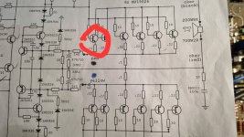
The first of the 6 pieces MJ15024 transistors from the positive wave is defective! The others look good! Of course I'm swapping the MJ15025 from the negative side too! Unfortunately they are no longer Motorola. But I don't think it will matter if they are swapped in pairs?
Attachments

I recently wanted to repair an amp with these transistors if I remember right, the replacement part measured quite different. I will have a look tomorrow, I may have a few real Motorolas left.
You need only one?
PS transistor amps are no cars. You don't need to change power transistors like tires, in pairs. They are OK or gone.
You need only one?
PS transistor amps are no cars. You don't need to change power transistors like tires, in pairs. They are OK or gone.
The output transistors need to be matched. The ones in your photo are the correct replacement. Motorola became ON Semiconductor.
You should remove the whole lot and measure them, this will tell you how "matched" these are.
The .22 Ohm emitter and 10 Ohm base resistors "match" the transistors.
Sorry, I don't have the same parts as yours, they are from the same family. Would have charged you P&P for one. The ones I got for a replacement measured quite different, so I did not repair the amp, as it was not worth the trouble.
So now I have swapped the two final transistors.
Unfortunately nothing has changed, the resistance on the front is still smoking. Final transistors remain OK!
Unfortunately nothing has changed, the resistance on the front is still smoking. Final transistors remain OK!
Repairing such an amplifier needs some practice, good knowledge, and (important) good equipment to check the specifications after repair.
Playing music "nice and fine" is absolutely no indicator for a successful repair.
I know that this opinion is polarizing,
Playing music "nice and fine" is absolutely no indicator for a successful repair.
I know that this opinion is polarizing,
You should be able to turn the amp on with a 75W dim bulb. Check the bias. If your amp is like the 23 there should be none because Vcc is too low.
Another check you can do is to measure resistance between the + and - Vcc buss bars. It should be an open circuit. If it isn't you still have a shorted transistor.
Another check you can do is to measure resistance between the + and - Vcc buss bars. It should be an open circuit. If it isn't you still have a shorted transistor.
- Home
- Amplifiers
- Solid State
- Please help me! Mark Levinson ML 23.5