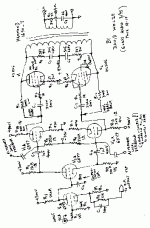
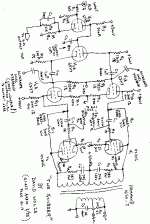
hey-Hey!!!,
We can create a few schematics...🙂 but I doubt there will complete agreement on its content. I owe my friend a schematic for use with 6AV5 finals, and this will be nearly the same.
cheers,
Douglas
We can create a few schematics...🙂 but I doubt there will complete agreement on its content. I owe my friend a schematic for use with 6AV5 finals, and this will be nearly the same.
cheers,
Douglas
"hey-Hey!!!,
We can create a few schematics... but I doubt there will complete agreement on its content. I owe my friend a schematic for use with 6AV5 finals, and this will be nearly the same.
cheers,
Douglas"
It looks that way, doesn't it! 🙂 Let's put something up on the board atleast, and try to get most to agree.
I finally found the article on "The Snubber" amplifier by David Wolze (Glass Audio 3/ 1995, pages 18 and 19)
It uses plate to plate local feedback to the drivers instead of Ultralinear mode, so is suitable for low screen voltage rated Horizontal output TV tubes. This is a more interesting circuit to me now that I am more familiar with local feedback designs. I may build this since I have the parts laying around, just to play with local fdbk. Maybe some others will pick up on this lost but interesting design too. The Hammond 1650T output transformer is readily available. Apparently the 42KN6 tubes drove this to full 120 Watt output in class AB.
Attached is a hand drawn schematic with an optional modification indicated to extend the local feedback back to the driver grids. (cross coupled to the driver grids like Thorsten advocates. Would require R11 and R12 to be increased significantly, maybe to 5 meg.?)
Don
Attachments
A couple more thoughts on using the alternative cross coupled local feedback mod. (to the driver grids)
Since the input impedance of the output tube grids will be much higher without the shunt feedback connection there, we could increase driver load resistors R10 and R13 significantly. (Have to compute the input capacitive Z of the output tubes at 20KHz. R10 and R13 must provide sufficient current for max 20KHz slew rate with some safety margin)
By the same token, connecting the local feedback (R11 and R12) now to the driver grids (C3,C4) will lower the impedance there. So the splitter loads, R6 and R7, should be lowered significantly (by the same ratio).
However, a low value for R7 will not drop enough DC voltage across it for the splitter tube grid to be direct connected to the input tube plate (R5). So I would dispense with the splitter setup and re-do the two input triodes to be a differential LTP with C3 and C4 then connected to their plates. The global feedback (C1 and R3) gets re-routed to one of the LTP grids then too.
Some experimentin' required.
Don
Here is another suitable NON-ultralinear design that could be easily adapted to the 6JE6C tubes. (the 1st schematic listed: "Very Basic Balanced Shunt Feddback")
http://www.turneraudio.com.au/miscellaneous-schematics2.html
The output xfmr primary impedance would need to be dropped about 1/2 I think for class A operation, and to about 1/4 for class AB. At least twice as many watts xfmr rating too, for class AB. The output tube screen grids would need a separate, roughly 150V, supply (preferably regulated) instead of connecting to B+.
The amplifier input appears to be a little insensitive at 3.08V, so you might want to graft on the 12AX7 pre-amp/splitter stage shown on the next schematic for an additional gain of 2x. (cap. couple 12AX7 plate and cathode outputs to both V3 and V4 grids to get 2X gain, like shown in the 2nd schematic. And needs another R5,R6 to ground for the V4 grid bias.)
The second schematic (same site) "Balanced shunt FB for 100W amp." looks interesting too. But hasn't been actually built. A particularly interesting mod. to this would be to connect the local FBK resistors to the 6BX6 pentode screens (instead of their plates), something like shown in the 3rd schematic. Would require some diddling with the FDBK resistors and some screen DC bias resistors to get the AC gain and DC screen idle voltages right. Also, the FDBK resistors would need to be cross-coupled (ie. swapped across tubes) due to the signal inversion between g2 and plate.
Here's a cross-coupled shunt feedback simulation schematic which could be modified for 6JE6Cs. Note that the 1 Meg. NFDBK resistors should be moved over to the 6SL7 plates. Output tube (6JE6C) screens would need a lower screen supply voltage, maybe 150V. And output xfmr primary impedance would need adjusting for the operating point chosen with the 6JE6Cs, probably more like 2K p-p in class AB.
http://www.diyaudio.com/forums/attachment.php?s=&postid=581214&stamp=1109054510
On constructing any designs with the 6JE6C tubes, I would keep in mind that replacement tubes in the future may be un-obtanium. So I would just solder-tack the components to the 6JE6C sockets (ie. don't wrap the wires around the socket pins tightly, or cut the leads too short). You may want to rewire them for another tube type later when necessary.
Don
- Status
- Not open for further replies.

