As an idea. Blameless + Sam Groner ideas+ inverting config + "a few poles compensation" gives something like this with a single pair of NJW0281/0302 in the output stage.
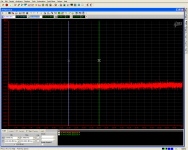
+24dBVrms for 90Hz, 1kHz и 10kHz (and 18dBVrms each for mix of 19.5+20.5kHz) @ 3.3Ohm
Levels on the spectra are absolute. As an example 2nd harmonic of 1kHz is around -139dBc
Will try to fins its .asc file at the evening.
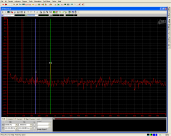
+24dBVrms for 90Hz, 1kHz и 10kHz (and 18dBVrms each for mix of 19.5+20.5kHz) @ 3.3Ohm
Levels on the spectra are absolute. As an example 2nd harmonic of 1kHz is around -139dBc
Will try to fins its .asc file at the evening.
Attachments

Last edited:
Found this long time ago, I think this was member T117 version of the Blameless design. Not sure though if it was actually built but I do remember that the designer mentioned fhe need for the 3 diodes in the LTP for a stable operation.
Sa muli,
Albert
Sa muli,
Albert
Attachments
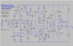
Main thing the cascoded VAS gets you is that the medium-power device is no longer so critical. This is the hard-to-get thing now - all the good CRT driver TO126's are obsolete. If you cascode, an MJE340/350 will work wonderfully.
The cascoded VAS looks interesting, in my simulation using the same VAS to other circuits OLG increases but I find it hard to balance the current as the negative rail clips earlier.
Simple solution to that is to cascode the VAS current source as well. That way it'll clip symmetrically. You lose a bit of headroom with this, but nothing worth worrying about
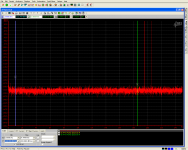
.asc file, following measurement results from the post #21
Placed models right on the schematic page, so you won't need a library.
Some of those modes are a bit dodgy, but close enough to illustrate the idea.
Placed models right on the schematic page, so you won't need a library.
Some of those modes are a bit dodgy, but close enough to illustrate the idea.
Attachments
Last edited:
Simple solution to that is to cascode the VAS current source as well. That way it'll clip symmetrically. You lose a bit of headroom with this, but nothing worth worrying about
jaycee,
Perhaps you are familiar with this circuit. I'm stuck with its clipping behaviour, can't figure out which part to adjust [running out of ideas here] It clips smoothly but the minus rail goes first. VAS is a folded cascode. Any tips and suggestion is fully appreciated.
Attachments
I'm not sure why you are concerned with a slight asymmetry of clipping.
Sergey,
I wanfed to see if there are improvements in the specs of a symmetrical behaviour [THD, Harmonic profile etc.]
I do know that some amps are deliberately designed with unbalanced LTP for example in order to display symmetrical clipping.
While there is some correlation between vas type and harmonic content (se stage more likely to produce somewhat higher even harmonics and clip a bit asymmetrically) you are overthinking the problem a bit. Is it a big problem if clipping produces a fraction more even harmonics? I don't think so, since there should not be clipping to start with. Moreover real signals do not usually have absolutely symmetrical swing.
Last edited:
One more consideration with regards to clipping - although the real music signal is not that symmetric, its average DC component is always close to zero. As soon as we enter asymmetric clipping, DC component moves towards the direction of higher swing. This is what I don't like about asymmetric clipping. I like it to be symmetric, clean and soft enough (rounded corners).
DC is a brother of even harmonics since even powers produce even harmonics and DC, but I still don't see any problem there 🙂
It is good to know if the problem with assymetric clipping is not that serious to the riding ac signal, maybe I was just thinking about maximizing the rail currents, that is uniform electron movements? Well just a thought though maybe I was just idealizing constant current constant voltage flow and its impact to THD...🙂
I once compared 2 circuits with the same design. One clips symmetrically while the other clips assymetrically. The symmetrical one had 0.01% THD and the assymetrical one had 0.002% THD both simulated at the same 1kHz freq at 60w average power. Could not remember though if their harmonic profile is dissimilar from each other.
I once compared 2 circuits with the same design. One clips symmetrically while the other clips assymetrically. The symmetrical one had 0.01% THD and the assymetrical one had 0.002% THD both simulated at the same 1kHz freq at 60w average power. Could not remember though if their harmonic profile is dissimilar from each other.
I guess you are mixing two separate things. If you are far enough from clipping, its asymmetry will not have affect on THD (while they still can be correlated).
For example post #21 spectra are measured less that a volt from clipping. They are not too bad to complain.
For example post #21 spectra are measured less that a volt from clipping. They are not too bad to complain.
Last edited:
On this matter can suggest to read Sam Groner's comments on Selfs book - quite a good stuff and a bit different point of view on a few things.
BTW it is not a JFET, it is an enhanced mode MOSFET.
BTW it is not a JFET, it is an enhanced mode MOSFET.
Last edited:
Yup, Groner's writings I had that one I also have his EDN articles of the push pull VAS concept. I've only seen one design that actually used Groner's formula, I think it was a symmetrical amp designed by member bimo. 🙂
- Status
- Not open for further replies.
- Home
- Amplifiers
- Solid State
- Please help improve Self's Blameless 50W amp