I'm looking for knowledgable people who would help me design (or rather design together) an improved 50W/8 Ohm amp based on D. Self's Blameless design. I'm not much into electronics, so I will need a lot of help and patience, I think.
I just read Self's "Audio Power Amplifier Design Handbook" 5th edition. From this I understood that his amp design is only "Blameless" until the quiescent condition of the output satge does not drift due to heating of the output transistors. But this quiescent state cannot be maintained well.
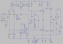
I attach Self's original circuit of his from page 209 of his book.
My "design" if I may say so is only incorporation of some ideas of Dado's ultra low distortion ThermalTrak + TMC amp to the Blameless amp.
My goal would be that with your help we could design a DIY amp that
-- Would give inaudible distortion at normal listening levels even if quiscent conditions in the output stage change with temperature and the amp becomes somewhat overbiased. By inaudible distortion I mean no distortion products higher than -100 dB even at 20kHz.
-- Would be stable and repeatable (no dependence on component tolerances).
-- Would be as simple as possible to facilitate DIYer build and fault finding (simpler than dado's design).
-- Use mostly readily and easily available components.
The changes I made so far to the Blameless design:
-- separate CCS for input LTP and VAS with increased current
-- OITPC compensation of the VAS according to Dado' design (although I increased most of the capacitors to have a lower loop gain f1 frequency. Dado's circuit with OITPC can be found here.)
-- A diode between VAS C-B for faster recovery from clipping
-- Voltage regulation on the negative supply, and RC filtering on the positive one
-- ThermalTrak output devices (although the present design of the Vbe multiplier is probably not optimal). This probably just decreases the possibility of thermal runaway and does not reduce distortion significantly, becase even slight overbias causes significatly higher distortion, and keeping very stable quiescent condition is not easy even with TT transistors.
Dado's design is very impressive and I'm not clever enough even to grasp most of the details, but IMHO for what reason should we have all distortion products below -140dB, if the highest SPL we listen to music probably never exceeds 100dB, and we hear nothing below 0dB SPL? So I think his design can be simplified without audible deterioration of sound quality. In Self's book its postulated that the input LTP with degeneration and current mirror and the VAS with buffer has low enough distortion levels to be inaudible with usual negative feedback factors. The main source of distortion is the class B output stage, which is worst if underbiased. A plan to bias the OPS into an slightly over than optimal bias, so crossover distortion should never occur. The takeover distortion (class AB) might come up to some degree, though the OITPC should minimize THD up to 20kHz. I think it's important for the distortion to be low even at 20kHz, because of difference distortion. (E.g. if you have a 19kHz and 20kHz signal, in a nonlinear system it will produce distortion at 20-19kHz= 1kHz.)
I've made an LTspice file (see attached), but I could not run the simulation so far, because I first will have to learn how to use LTspice.
Any comments or help is welcome, and you can modify and re-post the asc file, if you know what you're doing.
The only thing I ask is not to increase the complexity of the circuit significantly. Though an overload protection or loudspeaker protection may be necessary.
regards
Istvan
I just read Self's "Audio Power Amplifier Design Handbook" 5th edition. From this I understood that his amp design is only "Blameless" until the quiescent condition of the output satge does not drift due to heating of the output transistors. But this quiescent state cannot be maintained well.
I attach Self's original circuit of his from page 209 of his book.
My "design" if I may say so is only incorporation of some ideas of Dado's ultra low distortion ThermalTrak + TMC amp to the Blameless amp.
My goal would be that with your help we could design a DIY amp that
-- Would give inaudible distortion at normal listening levels even if quiscent conditions in the output stage change with temperature and the amp becomes somewhat overbiased. By inaudible distortion I mean no distortion products higher than -100 dB even at 20kHz.
-- Would be stable and repeatable (no dependence on component tolerances).
-- Would be as simple as possible to facilitate DIYer build and fault finding (simpler than dado's design).
-- Use mostly readily and easily available components.
The changes I made so far to the Blameless design:
-- separate CCS for input LTP and VAS with increased current
-- OITPC compensation of the VAS according to Dado' design (although I increased most of the capacitors to have a lower loop gain f1 frequency. Dado's circuit with OITPC can be found here.)
-- A diode between VAS C-B for faster recovery from clipping
-- Voltage regulation on the negative supply, and RC filtering on the positive one
-- ThermalTrak output devices (although the present design of the Vbe multiplier is probably not optimal). This probably just decreases the possibility of thermal runaway and does not reduce distortion significantly, becase even slight overbias causes significatly higher distortion, and keeping very stable quiescent condition is not easy even with TT transistors.
Dado's design is very impressive and I'm not clever enough even to grasp most of the details, but IMHO for what reason should we have all distortion products below -140dB, if the highest SPL we listen to music probably never exceeds 100dB, and we hear nothing below 0dB SPL? So I think his design can be simplified without audible deterioration of sound quality. In Self's book its postulated that the input LTP with degeneration and current mirror and the VAS with buffer has low enough distortion levels to be inaudible with usual negative feedback factors. The main source of distortion is the class B output stage, which is worst if underbiased. A plan to bias the OPS into an slightly over than optimal bias, so crossover distortion should never occur. The takeover distortion (class AB) might come up to some degree, though the OITPC should minimize THD up to 20kHz. I think it's important for the distortion to be low even at 20kHz, because of difference distortion. (E.g. if you have a 19kHz and 20kHz signal, in a nonlinear system it will produce distortion at 20-19kHz= 1kHz.)
I've made an LTspice file (see attached), but I could not run the simulation so far, because I first will have to learn how to use LTspice.
Any comments or help is welcome, and you can modify and re-post the asc file, if you know what you're doing.
The only thing I ask is not to increase the complexity of the circuit significantly. Though an overload protection or loudspeaker protection may be necessary.
regards
Istvan
Attachments

I think your logic regarding -100dB distortion is somewhat flawed. It's true that we hear nothing below 0dB (more or less) but that's in an INCREDIBLY silent room. If there's 100dB music blasting our ears, we most certainly cannot hear something down at 0dB. Most research I've encountered suggests we can pick out distortion in musical program around -25dB (for a 1kHz injected tone across normal playing levels, 80-100ish). It is highly frequency dependent, we can pick up a 10kHz tone as quiet as -40dB (again this figure is relative to the RMS music level) but around 40Hz the tone actually has to be *louder* than the music.
Now... this is just injected noise -- what we can pick up as "wrong". Harmonic distortion is a different story. The AES folks tell us that (especially for bass tones) significant masking occurs dependent, again, on program. We start picking up bass harmonics (against very loud program) conservatively around -60ish dB.
But more to the point, THD is more of a "eyebrow waggle" towards problematic distortion rather than a solid metric. People will argue me up and down, but results with CEA-2010 test tones (see D. Keale and a few other folks at Harman) suggest that bass is "good enough" at as much as -40db! These figures were used for internal quality control, mostly, to give a rough "pass-fail" metric... but still, it's suggestive of a lot.
Modern psychoacoustic models (sorry if I've lost you already...) like Rnonlin suggest that nonlinear distortion perception is based on expectation above all else -- we pick it up best in contexts where we have a clear idea of "correct sound." An interesting study was done at one point in a Psych journal (sadly I can't find it now...) that showed incredible levels of perception when the test material was a spouse's voice. One of the big papers on this (E. Santis, S. Henin) found that subjectively, THD (as well as IMD) were very poor predictors of audibility of distortion.
The big takeaway I got from their paper was brought up in the conclusion, that the fact that THD/IMD are highly correlated with signal levels royally interferes with an attempt to establish "good enough" let alone "inaudible" levels with these metrics.
So what do you do?
Assuming you don't have elaborate test equipment, lots of money, test subjects, etc. I see it as coming down to either: personal satisfaction (hard to predict before it's sitting in front of you), personal confidence (often gleaned from the knowledge that your design *should* sound good because it *is* good, right??? Someone must've thought so?), or external validation (the day I make an amp my partner likes, I might just quit.)
If that's not satisfactory, perhaps the flaw is in the definition of value: figure out why you are building the amp and then design it to do that.
Foof. That was long winded but at least I feel better having written it...
Looking at your requirements, I'd argue that it has already been done. Have a look at: http://www.diyaudio.com/forums/vend...mposite-amplifier-achieving-0-0004-thd-n.htmlI'm looking for knowledgable people who would help me design (or rather design together) an improved 50W/8 Ohm amp based on D. Self's Blameless design. I'm not much into electronics, so I will need a lot of help and patience, I think.
I just read Self's "Audio Power Amplifier Design Handbook" 5th edition. From this I understood that his amp design is only "Blameless" until the quiescent condition of the output satge does not drift due to heating of the output transistors. But this quiescent state cannot be maintained well.
I attach Self's original circuit of his from page 209 of his book.
My "design" if I may say so is only incorporation of some ideas of Dado's ultra low distortion ThermalTrak + TMC amp to the Blameless amp.
My goal would be that with your help we could design a DIY amp that
-- Would give inaudible distortion at normal listening levels even if quiscent conditions in the output stage change with temperature and the amp becomes somewhat overbiased. By inaudible distortion I mean no distortion products higher than -100 dB even at 20kHz.
-- Would be stable and repeatable (no dependence on component tolerances).
-- Would be as simple as possible to facilitate DIYer build and fault finding (simpler than dado's design).
-- Use mostly readily and easily available components.
The changes I made so far to the Blameless design:
-- separate CCS for input LTP and VAS with increased current
-- OITPC compensation of the VAS according to Dado' design (although I increased most of the capacitors to have a lower loop gain f1 frequency. Dado's circuit with OITPC can be found here.)
-- A diode between VAS C-B for faster recovery from clipping
-- Voltage regulation on the negative supply, and RC filtering on the positive one
-- ThermalTrak output devices (although the present design of the Vbe multiplier is probably not optimal). This probably just decreases the possibility of thermal runaway and does not reduce distortion significantly, becase even slight overbias causes significatly higher distortion, and keeping very stable quiescent condition is not easy even with TT transistors.
Dado's design is very impressive and I'm not clever enough even to grasp most of the details, but IMHO for what reason should we have all distortion products below -140dB, if the highest SPL we listen to music probably never exceeds 100dB, and we hear nothing below 0dB SPL? So I think his design can be simplified without audible deterioration of sound quality. In Self's book its postulated that the input LTP with degeneration and current mirror and the VAS with buffer has low enough distortion levels to be inaudible with usual negative feedback factors. The main source of distortion is the class B output stage, which is worst if underbiased. A plan to bias the OPS into an slightly over than optimal bias, so crossover distortion should never occur. The takeover distortion (class AB) might come up to some degree, though the OITPC should minimize THD up to 20kHz. I think it's important for the distortion to be low even at 20kHz, because of difference distortion. (E.g. if you have a 19kHz and 20kHz signal, in a nonlinear system it will produce distortion at 20-19kHz= 1kHz.)
I've made an LTspice file (see attached), but I could not run the simulation so far, because I first will have to learn how to use LTspice.
Any comments or help is welcome, and you can modify and re-post the asc file, if you know what you're doing.
The only thing I ask is not to increase the complexity of the circuit significantly. Though an overload protection or loudspeaker protection may be necessary.
regards
Istvan
and http://www.diyaudio.com/forums/chip-amps/267802-modulus-86-build-thread.html
As a side, I don't really care if my THD at 20KHz is -100dB or -10dB. Either way I'm not going to hear the harmonics (Or the fundamental for that matter)!
--> Uses 2SC3953 and complement, does not seem easily available (presumably EOL?)-- Use mostly readily and easily available components.
--> Uses 2SA970, known EOL
Ahem.
Some (bootstrapped) cascoding my be in order there if you really want to keep the "jellybean factor" high.
Compensation over the output tends not to appreciate capacitive loading very much, should be checked in sim.-- OITPC compensation of the VAS according to Dado' design (although I increased most of the capacitors to have a lower loop gain f1 frequency. Dado's circuit with OITPC can be found here.)
Why have you gone for 0.22 ohm emitter resistors rather than the 0.1s Self suggests?
Implementing some protection circuitry should be considered indeed, even if outputs seem generously sized (some commercial manufacturers use a single pair of 8 A transistors on over +/-50 V).
For maximum repeatability, a finished board layout would have to be provided eventually.
Rest assured you would not want an amplifier that is as bad as -10 dB at 20 kHz. It would still be very lousy at 6-10 kHz, and its HF IMD properties would be really bad. Not to mention that any kind of ultrasonic components as they tend to come out of DACs would have to be kept far away from it.As a side, I don't really care if my THD at 20KHz is -100dB or -10dB. Either way I'm not going to hear the harmonics (Or the fundamental for that matter)!
Thank you, Noah for the in depth reply.
That would mean that Self's original Blameless design is just more than good enough, even if the OPS bias creeps away from the optimal quiescent setting?
In fact I have never been part of a double blind amplifier test, but a few times listened to different power amps and I heard suprisingly big differences. It was not my expectaion to hear any, because I thought that the distortion of a loudspeaker is much higher than that of an amp. It surprised me though what I heard was that class A and valve amps sounded much better than run of the mill class B or AB. So it may not be the THD (as you say it's not a good metric) but some other distortion that is audible, or I simply was subjective?
Another thing which I hear on almost all recordings is that the sound is "not real", it sounds "electronic." Especially when many instruments are played at once, the sound becomes very unnatural and obtrusive. Whether it's because of the amp or the speaker or inherent in the recordings, I have no idea. If I look at THD performance alone, it must be the speaker.
Hi cowanaudio,
thanks for your suggestion. I have already found an interesting amplifier, Mike Ranardson's 7 transistor amp the MJR7-Mk5. There is also a PCB made by Livius. If I just want a good amplifier, I would choose that. It's simple, compact, and I can make the PCB's on my own. One of the reasons I started this thread that I don't much like the big output capacitor in the Renardson amp, although it may prevent loudspeaker damage in some fault conditions.
The biggest audible difference between power amps is frequency response. Second is output impedance (which causes frequency response wiggles). Blind tests have shown that if you equalise these, people cannot reliably distinguish one amp from another.
The sound of most recordings is not real, because it never was real. If you want reality you need to listen to acoustic music recorded with a coincident pair.
The sound of most recordings is not real, because it never was real. If you want reality you need to listen to acoustic music recorded with a coincident pair.
Hi sgrossklass,
Thanks for your comments. I have corrected what you proposed:
Changed 2SC3953 to KSC3503, and 2SA1538 to KSA1381.
Changed 2SA970 to BC556B.
Changed output emitter resistors to 0.1R.
Before I'd go further in improvements, I need to think if they are worth the increased complexity. I need some time to discover what kind of and what level of distortions are audible at all. It may well be that Self's original design is just good enough without any improvement.
If anybody wants to experiment with this in LTspice, here is the asc file.
Attachments
I built the blameless amp on the official boards when the design first appeared in Electronics World. It does what it claims although the recommended wiring layout for a two board stereo amplifier fed from a common PSU was far from blameless.
The vbe scheme works remarkably well if the sensing transistor is thermally coupled to one of the output devices which in my case were T03 packages. The bias was rock steady over any normal temperature range from within seconds of powering up to severely power testing into dummy loads.
Whether you like the 'sound' of the blameless configuration is another question altogether.
There are two mods I would do.
a.) add an RF filter to the input. 1k0 in series with the 10uF and a 680pF in parallel to the 10k.
b.) adjust the NFB dc blocking cap to avoid the added distortion created by using a too small capacitor. Self shows this specifically in Editions 2 and 6, I can't believe he omitted it from ed 5. >425uF and preferably >=680uF, maybe even using a 1mF
I would also look at adding degeneration to the VAS (you have added R4=22r) and a collector current limiting resistor to the EF driver at the VAS, maybe 1k0.
This will reduce open loop gain so you may have to use LTspice to work out how much to increase the Input LTP and VAS currents to restore the OLG.
I would definitely increase the Input LTP mirror degeneration. At least 300mVdrop across these resistors and even getting to over 600mV does no harm. So 150r with 2mA as a minimum, or 200r with 3mA is possible.
R31 is shown incorrectly and as a result the input wiring ends up wrong. Look at Bonsai's new amp wiring document, or read about HBRR+HBRL by D.Joffe.
Last edited:
Following on from DF's comment. After equalising the gains frequency response, some Designers claim that the main reason for hearing differences between amplifiers is in how they misbehave during and recovering from overloading, i.e. clipping recovery.The biggest audible difference between power amps is frequency response. Second is output impedance (which causes frequency response wiggles). Blind tests have shown that if you equalise these, people cannot reliably distinguish one amp from another.
The sound of most recordings is not real, because it never was real. If you want reality you need to listen to acoustic music recorded with a coincident pair.
I recommend having a look at D. Self APAD 6th edition, Chapter 7. There is a section called "VAS Distortion from Clamp Diodes" and Figure 7.12 shows distortion measurements with and without the clamp diode ("D2") in the attached schematic. May want to use the much lower capacitance 1N4149 or 1N4151.
_
_
Attachments

Last edited:
Hi AndrewT,
Thanks for suggestions! I made them except:
@jaycee
Thankx changed the VAS diode to BAV21.
There were 2 errors in the previous schematic, the SIN source was not grounded, and the quiescent current was very high (about 4 Amps)[/B] Here I upload the new asc file.
Thanks for suggestions! I made them except:
Is it to limit slew rateof input? I didn't add this because I read in Self's book that high input resistance adds significant "input current distortion" because of nonlinear input currents in the LTP. So this amp must be sourced from low impedance preferably < 200 Ohm. I've halved the feedback resistors (R23, R34) too, in light of this.a.) add an RF filter to the input. 1k0 in series with the 10uF and a 680pF in parallel to the 10k.
Somewhere I read that it's not good to put a larger resistance here, but I forgot the reason. Self says in his book that this R4 resistor is not really a degeneration resistor because the VAS is a transimpedance stage. Now I don't understand what he means (like I said I'm not really into electronics, but it would be nice if we could construct something nice together...)I would also look at adding degeneration to the VAS (you have added R4=22r) and a collector current limiting resistor to the EF driver at the VAS, maybe 1k0.
@jaycee
Thankx changed the VAS diode to BAV21.
There were 2 errors in the previous schematic, the SIN source was not grounded, and the quiescent current was very high (about 4 Amps)[/B] Here I upload the new asc file.
Attachments
balancing the source and feedback divider Z at the ltp +/- inputs gives some common mode nonlinearity cancelation - so if you intend to drive from a buffered source rather than a Volume Pot you can take this path
bootstrapped cascode of the ltp Q is more complicated but greatly reduces the input common mode distortion sensitivity to input Z
sharing the ltp ccs and VAS ccs ref turned out to be a poor idea for slew symmetry - later Self reversed them, added a positive feedback C to get symmetric slewing
Cherry gave an analysis of a single Q "VAS with degeneration" which suggested it was a wash gain/distortion wise but could give a high frequency phase margin improvment
Nobody wants to say anything positive (or negative) about R7 - C33 in the bias spreader? Nobody speculates that R16 is hooked up incorrectly: it wants to connect to R7 bottom instead of R7 top?
Generis69,
you should not miss Samuel Gronuer' paper, not quoted yet in this thread :
http://www.nanovolt.ch/resources/power_amplifiers/pdf/audio_power_amp_design_comments.pdf
you should not miss Samuel Gronuer' paper, not quoted yet in this thread :
http://www.nanovolt.ch/resources/power_amplifiers/pdf/audio_power_amp_design_comments.pdf
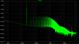
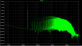
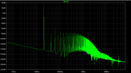
Nobody wants to say anything positive (or negative) about R7 - C33 in the bias spreader? Nobody speculates that R16 is hooked up incorrectly: it wants to connect to R7 bottom instead of R7 top?
Tnanks Mark, I wired it incorrectly. But I realized that if it's correctly wired (R16 connect to bottom of R7), then the THD performance at 20kHz (50W/ 8Ohm) is a lot impared. The lowest high order harmonics are when R7 is left out completely. See attached plots.
So what if I omit R7? I'm aware that it is there for better bias spreader stability, but most DIYers don't have a distortion meter to set the quiescent voltage optimally anyway, so why bother with this resistor?
Thanks for the other suggestions, but I don't want this design to be perfect in regard to distortion, only keep it as simple as possible for DIYers. My goal was only that the circuit should not have any distortion component at 20kHz higher than -100 dB, at power levels from 1W through 50W / 8 Ohm.
I will also upload the newest asc file with quiescent current 55 mA.
Attachments

Improve the blameless ? Simple. Cascode the VAS, use a triple darlington output stage, use split-pole compensation. Now get your layout good enough so that the THD improvements you'll get from all of those are not masked by THD caused by layout issues.
The original design performs far better with regard to distortion. If you are chasing numbers then I think you have your work cut out to imrove on the basic design.
Agreed, If I was "not much into electronics" as the OP said, I would just build the circuit as designed. Then look for improvements. And upon doing that one will quickly see how important RF layout techniques play into these micro distortion games - which BTW are a waste if time in the first place if you ask me.
- Status
- Not open for further replies.
- Home
- Amplifiers
- Solid State
- Please help improve Self's Blameless 50W amp