The top marking looks like Panasonic caps on the PCB that have been changed - though most don't seem to be seated evenly on the PCB, with most standing off the PCB surface.
Also Panasonic have used a M in a box symbol on most of their caps but now they seem to have changed that.
They use multiple caps to increase current capability and lower the combined ESR. In my MF A220 rebuild the original Jamicon main caps had a high current capability on the data sheet of about 5.2A but no derating so when I looked through the replacement caps data sheets I took a CDE with a 6.4A on the data sheet designed for 50/60Hz. I also used organic caps on the preamp power supply with 4000mA 10mOhm ESR in parallel to provide 8000mA however those have a serious 0.1 derating for low frequency but with ~20mA that's not a problem (it also powers the phono stage in the A220).
The stages are similar to the A220 - there's closer ±rail caps that have been changed in the board however the dumb bit is putting those massive caps in the preamp stage. It's unlikely to be using the charge capacity and for ESR it could be outclassed by modern caps. Did they replace the preamp opamp?
The two banks per side are one for +ve and one for -ve rails.
Now given those caps are sat on the toroid - I wonder how much amp is coupling the flux to the output stage.
many thanks chrisng!! 👍
as far as i can see, the smaller ones on the main pcb look like panasonics as well based on the very useful top/bottom markings chart you showed
as far as i can see, the smaller ones on the main pcb look like panasonics as well based on the very useful top/bottom markings chart you showed
Also Panasonic have used a M in a box symbol on most of their caps but now they seem to have changed that.
They use multiple caps to increase current capability and lower the combined ESR. In my MF A220 rebuild the original Jamicon main caps had a high current capability on the data sheet of about 5.2A but no derating so when I looked through the replacement caps data sheets I took a CDE with a 6.4A on the data sheet designed for 50/60Hz. I also used organic caps on the preamp power supply with 4000mA 10mOhm ESR in parallel to provide 8000mA however those have a serious 0.1 derating for low frequency but with ~20mA that's not a problem (it also powers the phono stage in the A220).
The stages are similar to the A220 - there's closer ±rail caps that have been changed in the board however the dumb bit is putting those massive caps in the preamp stage. It's unlikely to be using the charge capacity and for ESR it could be outclassed by modern caps. Did they replace the preamp opamp?
The two banks per side are one for +ve and one for -ve rails.
Now given those caps are sat on the toroid - I wonder how much amp is coupling the flux to the output stage.
man i have absolutely no idea what you're saying and asking, sorry for my ignorance ... i bought an amp that i did not know was modded, and the guy who sold it to me didn't do the mods, he claims he didn't know it was modded, his for sale ad did not show the innards, and he in turn had bought it only a few months earlier... well, at least it works very well and sounds really great...
So..... now that you have cleared this up, just discard all the negative comments. Put it back,
and let it sit quietly on it´s shelf, and enjoy the music, and that it sounds (as you say) really great 🙂
and let it sit quietly on it´s shelf, and enjoy the music, and that it sounds (as you say) really great 🙂

So..... now that you have cleared this up, just discard all the negative comments. Put it back,
and let it sit quietly on it´s shelf, and enjoy the music, and that it sounds (as you say) really great 🙂
have been all along, thanks
was just curious what was in it, how it was done, why... learned quite a bit from posting here, thanks to all
jjss49,
Welcome to diyaudio! Since this is a diy site, perhaps it's time for you to diy a case on each cap band to isolate them!

🤔 🙂
🙂
Welcome to diyaudio! Since this is a diy site, perhaps it's time for you to diy a case on each cap band to isolate them!
🤔
🙂tell me how chris? i am hopeless with my hands... except for writing checks and swiping credit cards... 🤣
i guess i could go to TAP plastics with dimensions have them make two little acrylic 'jewelry boxes' to put over those capacitor arrays? but then there is the issue of how to adhere them... (was kinda thinking what i might do instead is use some thin insulation padding and adhere it to the bottom of the black metal chassis lid of the amp, which goes over the cap arrays... but then i worry about that stuff touching the wires connecting the caps)... right now there is comfortable clearance over the tops of the caps, and the chassis cover is quite stiff...
i guess i could go to TAP plastics with dimensions have them make two little acrylic 'jewelry boxes' to put over those capacitor arrays? but then there is the issue of how to adhere them... (was kinda thinking what i might do instead is use some thin insulation padding and adhere it to the bottom of the black metal chassis lid of the amp, which goes over the cap arrays... but then i worry about that stuff touching the wires connecting the caps)... right now there is comfortable clearance over the tops of the caps, and the chassis cover is quite stiff...
From the photo I estimate those capacitors are about 1" or less in diameter, maybe you can cut four 1" wide plastic "u" channel sit on top to cover each array and glue it onto the side wall of those capacitors.

Or custom make two tall U channels same width of the wood boards, glue it onto the side wall of those wood boards.
 — S...png")
BTW, acrylic is non-conductive so no worry it touching the wires or those naked capacitors.
Or custom make two tall U channels same width of the wood boards, glue it onto the side wall of those wood boards.
BTW, acrylic is non-conductive so no worry it touching the wires or those naked capacitors.
1. Remove the caps, long term they might reduce transformer life.
2. You get PVC channels for wire trunking, and cable management in electrical panels, in many sizes, those should work as well or better than acrylic. And those have to meet electrical safety standards, and are easily available.

This is a representative image off the net, no links to seller.
2. You get PVC channels for wire trunking, and cable management in electrical panels, in many sizes, those should work as well or better than acrylic. And those have to meet electrical safety standards, and are easily available.
This is a representative image off the net, no links to seller.
Please ignore my post #28 and 30, I think it do more harm than good!1. Remove the caps, long term they might reduce transformer life.
👎🤐👎
yes indeed, some rubycons in there...
Hi jjss49 hope you're continuing to enjoy the A308.
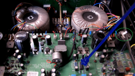
One thing to be aware of is that the aluminium strain relief clip for the mains cable is lying very close to the left power output stage. It should definitely be removed.
It should be (safely) attached to the top of C102 as shown in the second image.
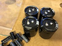
The four main PSU reservoir capacitors (one each for +60v -60v, left and right channels) were originally Jamicon LP 10000uF 63v. That is what has been replaced by the banks of seven Panasonics.
It is very common for them to degrade, as they operate extremely closely to the rated voltage (no derating) - third image shows those removed from my amp.
As NickKUK alluded to, I'd have added some screening between the new banks and the toroidal transformers.
If you need any original values/ratings or recommendations on improvements just ask, I've extensively modified my A308 and it sounds incredible for what it is.
One thing to be aware of is that the aluminium strain relief clip for the mains cable is lying very close to the left power output stage. It should definitely be removed.
It should be (safely) attached to the top of C102 as shown in the second image.
The four main PSU reservoir capacitors (one each for +60v -60v, left and right channels) were originally Jamicon LP 10000uF 63v. That is what has been replaced by the banks of seven Panasonics.
It is very common for them to degrade, as they operate extremely closely to the rated voltage (no derating) - third image shows those removed from my amp.
As NickKUK alluded to, I'd have added some screening between the new banks and the toroidal transformers.
If you need any original values/ratings or recommendations on improvements just ask, I've extensively modified my A308 and it sounds incredible for what it is.
Attachments


Unfortunately there is no bottom cover!I would not have used oak..!
I'm wondering why the hacker didn't replace those 4 big caps. (Then, those added caps would at least bring down the ripple, despite the long leads.)
Is there a bottom cover to access the pcb's underside, or does the whole amp need disassembling to reach the underside?
You're welcome to bring it over for a debrief, as you're nearby us in Novato?
It is necessary to remove top, rear and after unbolting the output transistors, at least one side heatsink in order to remove the PCB.
One other point is that the mains transformers also need to be removed to allow sufficient play for the board to come out. Going to be fun with the cap banks on top, but at least they unbolt from underneath.
Would walnut have sounded better?
- Home
- Amplifiers
- Solid State
- Please help identify these caps/mods in my Musical Fidelity A308 integrated amp