I have a pair of Audio Physic Caldera(30 years old speakers) that were passed down to me. A few years ago I tried to go active and gutted the bass crossover. Long story short, I want to put the oem bass crossover back because to me the original passive system sounded better with my 845 tube amp. It has been 5 years now, and I dont remember how the crossover were connected to the input(amplifier) terminals. The two pairs of black and red wires go to the woofers, but where is the inputs? Could you please take a look at the photos and help me? Thank you so much.
btw. This is a 3 way system. midrange and high have their own enclosure and crossover. Photos below are the bass/woofer crossover. Thx


btw. This is a 3 way system. midrange and high have their own enclosure and crossover. Photos below are the bass/woofer crossover. Thx
Last edited:
Very ugly certainly. You must have a low pass filter (L series and C shunt) for the woofer, a high pass (C series, L shunt) for tweeter. And possibly a bandpass for middle if any.
Hi thanks for your quick reply. The photo above showing the bass/woofer crossover only. The mids and highs have their own separate enclosure and crossover.Very ugly certainly. You must have a low pass filter (L series and C shunt) for the woofer, a high pass (C series, L shunt) for tweeter. And possibly a bandpass for middle if any.
Last edited:
So the 3 inductors are for bass only? Can you take a schematic at hand over paper and pencil and take a photo? Doesn't convince to me.


Thanks, so it would look something like this? I’m still a bit confuse. The negative terminal is connected to the woofers positive.If I am not mistaken, there is a 3rd order electrical LP (L ?mH, 400uF;2,66mH) and a series RLC (59mH, 2 resistors, 2 caps) in parallel with the woofers. Loudspeaker terminals are circled.
View attachment 1119679
Good idea. yes, this is the woofer part of the low pass crossover only. i do not know the the exact value, but here is the schematic. Thx again for your helps.So the 3 inductors are for bass only? Can you take a schematic at hand over paper and pencil and take a photo? Doesn't convince to me.
Last edited:
The woofer being out of phase with the input is unusual.
What's the phasing of the mid and tweeter?
What's the phasing of the mid and tweeter?
Hi, Mid bass and high frequency driver have their own separate enclosures, and their own crossovers. its really a pain to remove the driver to take a look the mid pass and high pass crossovers.The woofer being out of phase with the input is unusual.
What's the phasing of the mid and tweeter?
Ok, just keep the wiring the same as original.
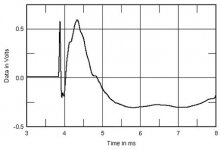
But according to this review, the woofer appears to be in phase with the input.
Also the tweeter is in phase, and the mid is out of phase. That's pretty normal.
https://www.stereophile.com/content/audio-physic-caldera-iii-loudspeaker-measurements
But according to this review, the woofer appears to be in phase with the input.
Also the tweeter is in phase, and the mid is out of phase. That's pretty normal.
https://www.stereophile.com/content/audio-physic-caldera-iii-loudspeaker-measurements
Attachments
Last edited:
I really appreciate you even going on the internet to help me find the answer. Thank you so much for your time. I don’t know how it is origina wired. I think your suggestion is the most likely the correct way, which looks like this correct?Ok, just keep wiring the same as original.
But acccording to this review, the woofer appears to be in phase with the input.
Also the tweeter is in phase, mid is out of phase. That's pretty normal.
https://www.stereophile.com/content/audio-physic-caldera-iii-loudspeaker-measurements
According to the test result, the woofer is wired in phase with the input.
That means it is reversed, in comparison with your drawing.
In other words, the woofer (-) should be connected to the input (-).
This is normal, and to be expected.
That means it is reversed, in comparison with your drawing.
In other words, the woofer (-) should be connected to the input (-).
This is normal, and to be expected.
Looks good. It is a low pass plus a series trap possibly at the resonance of the woofer.
I strongly dislike the placements of the inductors: all axes parallel. Too much magnetic coupling, which is undesirable.
I strongly dislike the placements of the inductors: all axes parallel. Too much magnetic coupling, which is undesirable.
this make a lot of sense. Thank you for this simple diagram. may I ask you one more question. The woofers negative terminals are wired after the 2 coils(Black wires in photo). So do I connect the negative terminal before the 2 coils like this?
You could do that, or flip both the input and the woofer.
The red input post is normally considered positive.
A positive voltage on the red terminal should cause the woofer
to move forward (positively), out of the enclosure.
In other words, the input black terminal should be connected to the (-) woofer terminal. This is standard.
Or, the input red terminal should be connected to the (+) woofer terminal. This is not standard.
But, either method will have the correct polarity.
Last edited:
This confuses me the most.You could do that, or flip both the input and the woofer.
The red input post is normally considered positive.
A positive voltage on the red terminal should cause the woofer
to move forward (positively), out of the enclosure.
In other words, the input black terminal should be connected to the (-) woofer terminal. This is standard.
Or, the input red terminal should be connected to the (+) woofer terminal. This is not standard.
But, either method will have the correct polarity.
- Home
- Loudspeakers
- Multi-Way
- Please help identify crossover input terminals