Hello fellow enthusiasts,
Im building a pair of 2way speakers for my garden and Im planning to use TXD-252 crossover that I bought online second-hand.
In the manual its is written:
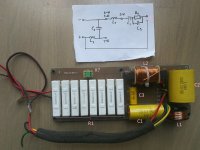
Please have a look at the pictures and help me identify how should I connect to get the "24dB/octave Linkwitz-Riley @ 1kHz". And what is this connection "X?" on the board?
Thanks
Rando
Im building a pair of 2way speakers for my garden and Im planning to use TXD-252 crossover that I bought online second-hand.
In the manual its is written:
- Passive: 12dB/octave high-pass and low-pass at 1kHz
- Active: 24dB/octave Linkwitz-Riley @ 1kHz
Please have a look at the pictures and help me identify how should I connect to get the "24dB/octave Linkwitz-Riley @ 1kHz". And what is this connection "X?" on the board?
Thanks
Rando
Attachments
If you want to operate your speaker actively, e.g. by using a DSP controller,in order to use one power amplifier each for the high and low frequencies, then you don't need the passive crossover at all.
But maybe I didn't understand the question correctly?
Many greetings,
Azrael
But maybe I didn't understand the question correctly?
Many greetings,
Azrael
Thanks Azrael for your reply! I think you understood correctly.
Lets focus on the passive crossover.
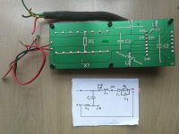
Looking at the pictures.
If 1-N & 1+N are for subwoofer and 2-N & 2+N are for tweeter horn, what is the purpose of C1, R1 and C3? And the "X? that breaks the electrical curcuit"
2-N & 2+N locate on another sode of inductance L1, it doesnt quite look like a curcuit to me..
Lets focus on the passive crossover.
Looking at the pictures.
If 1-N & 1+N are for subwoofer and 2-N & 2+N are for tweeter horn, what is the purpose of C1, R1 and C3? And the "X? that breaks the electrical curcuit"
2-N & 2+N locate on another sode of inductance L1, it doesnt quite look like a curcuit to me..
X connects the input of the tweeter crossover to the input of the woofer crossover. This way the incoming signal will supply both of them.
C1 is the standard high pass filter component. C3 and R1 provide an upward tilt to the higher frequencies.
C1 is the standard high pass filter component. C3 and R1 provide an upward tilt to the higher frequencies.
Thanks Allen!
So in case I want to feed both tweeter and woofer from singe input I should bidge the gap X? Otherwise it feeds only the woofer?
And then to connect the drivers to pins 1-N & 1+N and 2-N & 2+N?
So in case I want to feed both tweeter and woofer from singe input I should bidge the gap X? Otherwise it feeds only the woofer?
And then to connect the drivers to pins 1-N & 1+N and 2-N & 2+N?
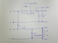
It a passive/biamp crossover. I do not know if the woofers will be connected in series or in parallel.
Attachments
Last edited:
Anyway, this passive crossover is only useful if the original drivers are used in the original cabinet. Is that the plan?
Many greetings,
Azrael
Many greetings,
Azrael
Thanks for thinking along and for the drawing!
I have built my own cabinet 125 x 30 x 30 cm out of 1.8cm waterproof coated plywood and planning to use the following drivers:
MCM 53-1225 dome horn tweeter:
10" waterproof marine woofer (Im building outdoor speakers for garden use):
As TXD-252 crosses over at 1kHz I thought I could work out.
Perhaps I should put a 50W 12 Ohm resistor in series with the tweeter to damp it down a bit.
Another option to use the woofer without a filter and use a 10uF capacitor and a resisotr in series with the tweeter.
How do you think?
I have built my own cabinet 125 x 30 x 30 cm out of 1.8cm waterproof coated plywood and planning to use the following drivers:
MCM 53-1225 dome horn tweeter:
- High Compliance Response:1K-20KHz
- SPL:100dB@1W/1M
- 200 Watts Rated Power
10" waterproof marine woofer (Im building outdoor speakers for garden use):
- RMS: 250W
- Max: 500W
- Frequency response 30 - 1000 Hz:
- Sensitivity dB: 92
As TXD-252 crosses over at 1kHz I thought I could work out.
Perhaps I should put a 50W 12 Ohm resistor in series with the tweeter to damp it down a bit.
Another option to use the woofer without a filter and use a 10uF capacitor and a resisotr in series with the tweeter.
How do you think?
Attachments
The crossover will have been adjusted to match the acoustic roll off of the drivers it was designed for. Unfortunately the chance of that being the same as the drivers you have chosen it almost zero.
This means this crossover will probably work to protect the drivers from damage and it will band limit the drivers to some unknown response. However the chance of the Bass and Tweeter responses matching up in phase and to a flat response is again almost zero.
Since you have it, you might as well put it together and see how it sounds, the human ear can be surprisingly forgiving to frequency errors. If it sounds dreadful, you will need to find someone with speaker measurement equipment. Take some measurements of frequency response and impedance ( resistance with varying frequency) and then go up the very steep learning curve of crossover design or see if someone will show you how.
Alright, so that means all pre-manufactured generic audio filters are waste of resources right?
As I understand in every case the crossovers should be designed together with drivers as each driver has its own reactive inductive resistance even if the active part of the impedance is the same?
So what wouls be the rigth approach, to measure the inductance of the drivers and put them into electical circuit to calculate the roll-offs, resonances, ect?
And based od that to buy inductors, capacitors and resistors and build cossovers form scratch? And to forget about all the existing crossover filters out there?
Unless they are designed for a specific driver combination in a specific cabinet: yes.Alright, so that means all pre-manufactured generic audio filters are waste of resources right?
As for the rest: no, crossover designs are not based solely on the impedances of the drivers involved. Each driver also brings different acoustic frequency responses, which are also very much affected in different ways by the cabinet they are installed in.
Many greetings,
Azrael
You can get some idea of what to do reading the sticky threads on designing a speaker from scratch and designing without measurements.
Hello again.
By now Ive built the cabinets and attached the dribers and made some tests with biwiring and crossovers outside of the box.
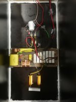
What Ive done now is Ive put this crossover inside the box and added 70ohms of resistance in series with the tweeter in order to reduce its loudness compared the woofer. Woofer cabinet is closed.
I have two questions:
1. What happens to the sound if I solder off one of the 40ohm resistors and the total resistance will be 5.7 ohms instead of 5?
2. How sould I make the biampwiring? I have 4 pin terminal. Should I add a switch that disconnects the bridge X and connect another set of wires from the second pair of terminals with the tweeter?
Thanks
By now Ive built the cabinets and attached the dribers and made some tests with biwiring and crossovers outside of the box.
What Ive done now is Ive put this crossover inside the box and added 70ohms of resistance in series with the tweeter in order to reduce its loudness compared the woofer. Woofer cabinet is closed.
I have two questions:
1. What happens to the sound if I solder off one of the 40ohm resistors and the total resistance will be 5.7 ohms instead of 5?
2. How sould I make the biampwiring? I have 4 pin terminal. Should I add a switch that disconnects the bridge X and connect another set of wires from the second pair of terminals with the tweeter?
Thanks
Attachments
- Home
- Loudspeakers
- Multi-Way
- Please help figure out the TXD-252 crossover by Turbosound