as for speaker placement its most likely going to be in a corner on my desk. what kind of considerations should i be aware off when designing the speaker?
Speakers and corners don't exactly mix together well. Any inside corner is going to have an amplifying effect (like a megaphone) on the bass much more than on the treble and it's going to sound really bad. To get some idea go stand in a corner and say a few words... note what it does to your voice? Ya...
If it's at all possible you want to keep your speakers out of corners and some distance from the wall as well. If these are desktop speakers you may even want to raise them off the desktop to prevent effects from the table itself.
If it has to be a corner location and because its a 5" driver you may get away with it simply by having very little series inductance to the bass, i.e. almost no diffraction loss compensation.
Douglas's point is a warning of what can very easily go wrong.
If you do manage to make it work in a corner position, I think you will, you are about to learn that if you make a change in one part of the frequency spectrum that effects the overall balance you may have to make a corresponding change in the tweeter section either on overall level or slope. Its great fun and you will only get better at it the more you do. Just like everything else in life.
Design or make a change, double check it, listen and take you time, give every change a write up in a logbook and listen to a change for at least a day with your favourite music, go to bed and then listen to it again in the morning. Write up your impression or commit to memory. Even with measurements I like to give it a day to settle in.
Hello there thanks for the advice everyone. I've been having a play on Xsim and was wondering if anyone would be willing to have a look for me. I've gone through quite a few different variations, different orders etc. and this is the best I have been able to get it. I've mainly been focused on achieving as flat a frequency response as possible. If anyone can see any faults in the other areas like impedance, baffle step and power response it would be greatly appreciated as i'm still unclear what i'm looking for in these areas.
The only question I have specific to my design is whether I would benefit from an Lpad instead of the single in series resistor on the tweeter. And if so what would be the benefit? Is an Lpad always a better option?
If there aren't any reasons why i shouldn't build please let me know because i would love to get to building. Cheers thanks again
Ps. please let me know if my attached file doesn't appear and please feel free to make any changes to the file to help illustrate where improvements can be made.
Attachments
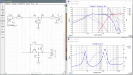
Pic 1 is your xo. I've circled a few things which need attention. First it looks like you included baffle effects which is good but you also have to include minimum phase for both frd and zma files - choose 'derived' - and you need to include an estimate of the delay for the woofer which could be about 1/2" to an inch or so. Real measurements are the only way to be totally accurate with this but a guess here looks like it should work fine, ie. phase isn't changing too too much within the parameters I mentioned above.
In addition impedance is too low at about 3kHz - due to L2 being too small and C1 being too large. Also phase does not line up well in the xo region. Going 3rd order electrical on the tweeter will often fix this. And the woofer looks like it has a bad resonance around 6kHz so it might be wise to do something about that.
Nothing wrong with just series resistance on the tweeter btw.
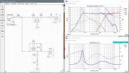
Pic 2 is a re-do with your files and all the corrections mentioned.
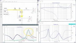
Pic 3 shows how the xo might have to change if the speakers are in corners or right up against a wall. I re-did the files to include baffle effects but without any baffle step loss. I added in the vented response to the woofer but didn't change the impedance file because it doesn't make much of a difference in the sim. Speaker placement will determine which xo sounds best.
The XSim files are attached. Go through them and short and/or remove components to understand what they are doing. R1 is not really a real component. I now use it as a tool to look at the current that the system is using. Choose 'AddGraph' -> more -> Component Current to get the chart, increase the power to actually see what's happening and choose the 1Amp scale. The Power Dissipation chart can be useful to look at as well but you kind of have to know the max power you will use on the speaker and that there is always less power being used as you go higher in frequency.
In addition impedance is too low at about 3kHz - due to L2 being too small and C1 being too large. Also phase does not line up well in the xo region. Going 3rd order electrical on the tweeter will often fix this. And the woofer looks like it has a bad resonance around 6kHz so it might be wise to do something about that.
Nothing wrong with just series resistance on the tweeter btw.
Pic 2 is a re-do with your files and all the corrections mentioned.
Pic 3 shows how the xo might have to change if the speakers are in corners or right up against a wall. I re-did the files to include baffle effects but without any baffle step loss. I added in the vented response to the woofer but didn't change the impedance file because it doesn't make much of a difference in the sim. Speaker placement will determine which xo sounds best.
The XSim files are attached. Go through them and short and/or remove components to understand what they are doing. R1 is not really a real component. I now use it as a tool to look at the current that the system is using. Choose 'AddGraph' -> more -> Component Current to get the chart, increase the power to actually see what's happening and choose the 1Amp scale. The Power Dissipation chart can be useful to look at as well but you kind of have to know the max power you will use on the speaker and that there is always less power being used as you go higher in frequency.
Attachments

Your impedance dips below 2 ohms. Your tweeter filter is of too high a Q factor. Your phases are 90 degrees apart, not that there's necessarily anything wrong with that but on average I'd be looking to bring them closer. With regards to power, I wouldn't buy too heavily into the breakup peak just keep it down, otherwise there's nothing obvious.like impedance, baffle step and power response it would be greatly appreciated as i'm still unclear what i'm looking for in these areas.
WRT the baffle, did you measure your woofer in its box, is the measurement clean?
If it does the job. Sometimes it is easier with an L-pad.The only question I have specific to my design is whether I would benefit from an Lpad instead of the single in series resistor on the tweeter. And if so what would be the benefit? Is an Lpad always a better option?
Don't do this. The delay is already in the measurement (and it's closer to 7.5mm).but you also have to include minimum phase for both frd and zma files - choose 'derived' - and you need to include an estimate of the delay for the woofer which could be about 1/2" to an inch or so.
I think you should be happy with your efforts.
jReave and AllenB has picked up on the few points, and changes in those areas really start the process of fine tuning the design to be really good one.
The updated Xsim files look to be the business, and at the same time the parts count is still low, which is good.
With the crossover simulating so well, make the choice of speaker location build a suitable crossover and start listening. Some component tuning should give you a really fine speaker. In terms of listening and tuning one component at a time.
I'm not sure I can agree. It is my understanding that the OP got the frd and zma files from Impulse Audio (youtube channel, link posted here before). I had a look into the videos, and found the procedure for the measurement. For the tweeter, the baffle is 8"x14" and the tweeter is centered at roughly 87mm from top. For the woofer I didn't find the baffle measure, but from the look at least the width is the same. So if the OP choose a similar baffle and similar tweeter layout, he can use the frd files without changes for the SPL values.Don't do this. The delay is already in the measurement (and it's closer to 7.5mm).
I don't know how to use the phase data in the frd files, however. I'm not sure that the phase is consistent between the tweeter and woofer measurements, so if I'm not missing something I think you have to add the appropriate delay to the woofer. Unfortunately at the crossover frequency the delay is what can bring the two drivers in phase or not.
Ralf
Thank you. I should retract my comments regarding delay. Regarding either removing the delay or selecting minimum phase, either way will be a compromise.I'm not sure I can agree.
Wow! Thanks everyone for the informative responses.
I have a few questions about the issues raised concerning the crossover. Theres a few so bare with me, i'm hoping that your answers will help make me a more independent designer.
1.impedance ? : The impedance was identified as being too low.
2.Q factor? :
3.Phase? : Forgive me for this one but how do you read phase from a graph😕😱? I dont quite understand how degrees are translated into phase difference.
4.Adding delay? :
I completely understand there's a lot to answer any knowledge you can give me will be greatly appreciated. Also any recommendations of articles or books that would be good for me to read will be equally appreciated.
Thanks Jreave for those files really useful having a practical example to play with and Thanks again for everyone's contributions once again blown away buy the helpfulness of this community cheers!
i didn't personally make the measurements but yes they where made in the box which i have dimensions for. What do you mean by clean?did you measure your woofer in its box, is the measurement clean?
I have a few questions about the issues raised concerning the crossover. Theres a few so bare with me, i'm hoping that your answers will help make me a more independent designer.
1.impedance ? : The impedance was identified as being too low.
What are you looking for in an impedance graph and how do you identify issues? Is it simply because it's below the rated impedance of the tweeter? how will impedance issues affect a system?Your impedance dips below 2 ohms
is there a desired ratio between these components or minimum and maximum rating for each component?impedance is too low at about 3kHz - due to L2 being too small and C1 being too large
2.Q factor? :
. How do you determine Q factor and how do you identify when it is two high or low? Is Q factor determined by the ratio between inductors and capacitors?Your tweeter filter is of too high a Q factor
3.Phase? : Forgive me for this one but how do you read phase from a graph😕😱? I dont quite understand how degrees are translated into phase difference.
. What should I be aiming for when designing a crossover?Your phases are 90 degrees apart
4.Adding delay? :
. Where does this measurement come from and how do I find it?include an estimate of the delay for the woofer which could be about 1/2" to an inch or so
I completely understand there's a lot to answer any knowledge you can give me will be greatly appreciated. Also any recommendations of articles or books that would be good for me to read will be equally appreciated.
Thanks Jreave for those files really useful having a practical example to play with and Thanks again for everyone's contributions once again blown away buy the helpfulness of this community cheers!
1.impedance ? : The impedance was identified as being too low. What are you looking for in an impedance graph and how do you identify issues? Is it simply because it's below the rated impedance of the tweeter? how will impedance issues affect a system? is there a desired ratio between these components or minimum and maximum rating for each component?
Impedance is all about keeping your amp happy. Amplifiers are usually rated for either 8ohm and/or 4ohm nominal loads which in reality mean minimums of 6ohm and 3ohm respectively. If your speaker impedance drops below those levels somewhere, remember impedance is simply resistance at each frequency, it will mean current will be flowing too freely at whatever frequency we are talking about. Raise the power too high and that could ruin the amp or shut it down or simply blow a fuse. Because every amp has an upper current limit. The equations are pretty simple:
P = RI^2 so I = SQRT(P/R)
So if you have a 100W amp rated into a 4ohm load, maximum current is 5 amps. Feed a 2ohm load with just 60W and boom, you are looking at a current of 5.47 amps. Not good.
So if it's current that's important, how do you keep your eye on it? Take a look in XSim: AddGraph -> more -> Component Current. Increase the power and change the vertical scale to 1A so you can see what is going on, and add a series resistor of the tiniest value (.1ohm) in front of everything. Now that resistor will show you the speaker's overall current consumption and you can compare this with the current the drivers and individual components are seeing as well.
Pic 1 below shows the skyrocketing currrent that is flowing through L2 at about 3kHz in 1 of your previous xo's. Perhaps it helps to understand what is happening electronically. C1 is large enough that it is letting the whole upper frequency range through and only blocking the lowest frequencies. L2 is small enough that it is letting almost all the LF's through and only blocking the highest ones. That means you've got too large a percentage of frequencies going straight through C1 and L2 to ground and not enough getting to the actual driver. The path is too conductive in other words and not resistive enough. And a path to ground that has no resistance has a name you should be familiar with - it's called a short circuit.
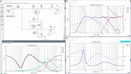
Pic 2 is a corrected version. The problem at 3kHz has been mostly fixed but notice that there is still a little wasted current, as L2 is still showing more current going through it than is going through the tweeter. A little inefficiency that most amps should be able to live with.
3.Phase? : Forgive me for this one but how do you read phase from a graph😕😱? I dont quite understand how degrees are translated into phase difference. What should I be aiming for when designing a crossover?
If you want to simplify things, you can completely ignore the phase degrees. What you are trying to do is get each driver's phase to be about the same in the xo region where the 2 drivers' FR's overlap. The phase relationship is about timing. You simply want both drivers' sound to arrive at your ears at the same time. In phase (timed together) and they add properly. Out of phase and they don't. Line up the phase curves in the xo region and you will be good.
Helpful tips:
- adding components changes a driver's phase/timing
- changing the component values does the same thing
- reversing driver polarity changes the phase hugely, specifically 180 degrees so instead of the driver moving out, it's moving in. The wave isn't a peak but is a trough instead.
Now if you want to look at phase degrees in the XSim FR chart, the scale is on the right. In pic 1 again, your woofer phase at 1kHz is at about 45 degrees. Your tweeter phase at the same frequency is at about 135 degrees. Thus a 90 degree difference. Where the tweeter phase goes straight vertical is just a function of the charting method - the phase is continuing to decrease but the chart can't show it so it wraps around to the top and continues decreasing again.
4.Adding delay? : . Where does this measurement come from and how do I find it?
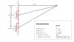
Adding delay is again about timing and mostly it's about geometry. We can't figure out what the driver phase is is we don't know exactly where in space it's originating from, ie. the driver's acoustic center. The correct way to determine this is through measurements with a mic. The alternative for simulation purposes is to take our best guess with a couple of rules of thumb (which aren't always right) and then do some calculations.
First the rules of thumb. For acoustic centers with tweeters, the rule of thumb for a standard tweeter is at the bottom of the faceplate, so about 5mm back for your tweeter. For the woofer, the rule of thumb is at about where the voice coil meets the cone, most commonly where the spider is. Measuring from the spec sheet diagram, that's about 30mm back. So the difference in acoustic centers is about 25mm.
Now for the calculations. What we are trying to determine in XSim is the difference in pathlength from our ear (or a measurement mic) to each driver's acoustic center. Pic 3 below displays the geometry and the necessary equations to do the calculations. Basically we are just working with right angle triangles. As such, the distance between drivers and the distance to the listening position will affect the results. So let's say we have about a 5.5" height difference between your drivers and a 1m listening distance. Doing the calculations, the woofer delay works out to about 1.35". At 2.5m, the delay will be about 1.1". Recently, I've seen that the woofer acoustic center can be a little forward from the rule of thumb so the actual delay is smaller. Thus I took a guess and said try 1/2"-1". Change the delay value up in XSim and see how it affects your phase alignment in the xo region. Maybe a middle value like 1" is best so that if you are off 1 way or the other, you will still be pretty close. Changing the 2nd capacitor, C3, on the tweeter is probably the easiest way to adjust the phase alignment without changing the FR too much.
Sorry, kind of lengthy but those were good questions.
Attachments
Loudspeaker Design Cookbook: Amazon.co.uk: Dickason, Vance: 9781882580330: BooksAlso any recommendations of articles or books that would be good for me to read will be equally appreciated.
I actually find that book to be way over the head of beginners.
Ray Alden's Speaker Building 201 I find much more approachable but even better for a newbie is wintermute's stickie, So you want to design your own speaker from scratch!
Ray Alden's Speaker Building 201 I find much more approachable but even better for a newbie is wintermute's stickie, So you want to design your own speaker from scratch!
Yes, the David Weems book (mentioned by wintermute) would be a better starting point.
Again, available in the UK here: Designing, Building, and Testing Your Own Speaker System with Projects eBook: Weems, David B.: Amazon.co.uk: Kindle Store
Again, available in the UK here: Designing, Building, and Testing Your Own Speaker System with Projects eBook: Weems, David B.: Amazon.co.uk: Kindle Store
Picking a 1 inch offset between acoustic centres is a suitable approximation.
SB Acoustics publish some data for some of their driver pairings, have a look at their webpage and yes 1 inch is probably the average value.
The way the bassmid driver basket raises the position of the cone, the cone shape, along with surface / flush mounting the driver determines its baffle related acoustic offset. Bassmids have the most variations, obviously.
Tweeters tend to have much less variations, with the exception of horn tweeter with the dome set back in the throat of the horn. There have been a few designs where the tweeter horn offset have provided a good phase match.
Troels Gravesen site has a range of stepped baffles with the idea that the additional 18-22mm baffle material for the bassmid more closely aligns phase between the drivers and simplifies crossover design.
To keep costs down, more so in the past, a lot of bassmids and tweeters were not flush mounted. More recently most tweeters are flush mounted, flush mounting the tweeter helps smooth tweeter diffraction and at the same time can lessen the acoustic offset by a few millimetres, typically it will be never enough unless you are extremely lucky with the drivers chosen.
With the current proposed crossover and the possibly of a less than perfect phase match, you frequency response will show differences between the modelled data in the crossover region. This may in fact be beneficial and can be used to give you a dip in the range 2-3Khz which some people suggest, and many seem to like.
When you first build your design, you will have an opportunity to reverse the connection to one of the drivers. It will introduce a change, you can measure it with good equipment, but depending on its shape and frequency range can you hear it? Small dips are not so discernible to our hearing mechanism.
A good modelled response, is no guarantee you will find the sound satisfying, you may still need to tune some of the component values.
Last edited:
amazing! once again blown away thanks again for all the help. I've purchased all the components needed but as I don't really have access to many useful tools at the moment so it may be some time until I get to build it. all the support and information has been incredibly useful and inspirational. cheers
- Home
- Loudspeakers
- Multi-Way
- please help a beginner with some questions