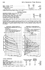
I have a pcb for the attached schematic. Right from the output of the 6x4 regulator, the silkscreen on top of the pcb shows a 20 ohm resistor and the bottom shows a silkscreened choke (no value). Pics online show the resistor. Neither are on the schematic. I have built 6 tube supplies, all with chokes, all cap input. The pads here would make this choke input. I plan on using the choke, not the resistor, for choke input to load. Then there is the rest of the supply. Let’s come back to that.
SO, to find the correct choke using the tube data sheet for a choke input supply, here are my calculations for a 6x4 tube. I have never used this before but shows little sag at any permissible voltage:
Transformer that I have is 600v center tapped
Vload=270
Iload=15ma x 4tubes=60ma
Vmains=120
Fmains=60hz
Avg current per plate- Iplate= Iload/2= 60/2= 30 ma
Peak current per plate- 4Iplate= 4x30=120ma
*max plate current for this tube is 220 per plate
Peak inverse voltage
v=(1+rt2)vload
v=2.41*270
v=650v
*max inverse voltage for this tube is 1250v
Here is where things get sketchy for me. How do I interpret the x axis on the graph, which is labeled “dc load milliamperes”? Is this average, average per plate or load current?
At the bottom, it shows typical operation for 400volts input @ 70mv load requires a 10 hry choke. I can’t reconcile that against the chart.
I have no idea what size these files will end up as so let me know if there is an issue. Thanks.
Attachments
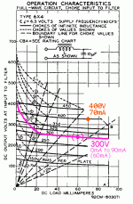
Thanks so much. That is how I interpreted the graph for my project. But, how do they recommend 10hy in the typical application? You would still be in the 3h range.
I have only every used tube data sheets to build a supply. The supply in the schematic is nowhere near what I have built before. I should be able to work out the voltages at the nodes. But, the data sheet calls for a 10uf cap after the inductor. This schematic shows 100uf. I'm leary of overbuilding the capacitance as I don't know what effect this will have on the peak current draw. I don't want to kill the tube. Will all the regulation keep this tube in its operational range?