Hi, Here is a source follower from a Melos SHA1
The source followers have a double diode connected between G and S. I need this double diode but can't identify the part number, Do someone knows what it coule be ?
Also, what is the purpose of this double diode and how it works ?
Thanks

The source followers have a double diode connected between G and S. I need this double diode but can't identify the part number, Do someone knows what it coule be ?
Also, what is the purpose of this double diode and how it works ?
Thanks
The diodes are for gate/source protection. I assume these are lateral FET's
I seem to recall 8v2 Zener's being a typical value and they are used in series with a 1N4148. Note the polarity of the diodes with respect to the N channel and P channel FET's they protect. They clamp the G-S voltage to 8v2 +0.6 in one direction and have no effect in the other direction (appear open).
This shows a typical arrangement.
The diodes are there to protect the FETs form excessive gate-to-source voltage, which might occur on startup, turn-off or transient signal conditions.

Might be a TVS, but I am confused by your schematic symbol,internalZeners are in series, not diodes in parallel.
That said, I already found on comment about proper symbols being oftn ignored,so ...
In any case, you want something which clamps voltage to less than 20V (which is a typical Vgs breakdown voltage), both ways for 100% safety.
Personally I use a 1N4148 in series with an 8.2V Zener across GS in the IRFP250/240 I use in my Musical Instrument power amps and it works fine, but of course would be as happy with a symmetrical array.
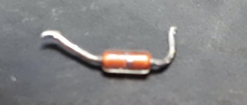
That is a diac. It is a by directional avalanche breakdown device. Threshold typically 30v but also ranging down to around 10v, either direction and only several volts conducting with a holding current of a few mA. The primary use is as a AC mains trigger for thyristors.As I would like to use what's inside in other places, here is a picture. The part has a gold line in the center
Thanks a lot. Is there any advantage to use them instead of using zener diodes ? Less capacitance etc ?
Diacs are fundamentally different to Zeners. A Zener begins to conduct when the voltage across it reaches its marked value. The Diac also does this but once conduction starts the device drops to a low impedance condition and conducts heavily until the current flowing falls below some predetermined value. Diacs are also bidirectional.
So if they are Diacs then you can not really make those from Zeners.
Are you sure the circuit is drawn correctly because G-S Zener protection is common but I've never seen or heard of Diacs used with FET's.
So if they are Diacs then you can not really make those from Zeners.
Are you sure the circuit is drawn correctly because G-S Zener protection is common but I've never seen or heard of Diacs used with FET's.
^^^^^^^ that.
Using a DIAC there gives me the shivers: uncontrolled, BRUTAL negative impedance clamping action, quite undefined trigger and clamp-to voltage, ugh!!!!
I´ll take a Zener any day of the week.
You use, say, a 12V one, you know it will not let anything above 12.1V, will remove itself from the picture at 11.9V ...or thereabouts.
A Diac is completely unpredictable, unless, say, pretested before use.
But hey, Designers often have their own pet ideas.
- Home
- Amplifiers
- Tubes / Valves
- Please can you identify this part