My electronic crossover, a/d/s/ 642ix, utilizes switchable modules for changing the crossover frequency. The modules require to change capacitors and resistors.
I’m going to use it with three-way speakers. So, I need to modify the modules.
Attached is the instruction for modifying the modules.
I found my existing module has different component values to the instruction manual. They are as follows:
C1, C4 = 332G (I guess it’s about 3.3nF)
C2, C3 = 562G (I guess it’s about 5.6nF)
R = 20k Ohms
1M = 3M Ohms
I need help to reverse engineer this module. Which frequency it was designed? And what formula to modify it to the desired frequency?
Attachments
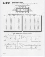

I'm getting a different result than Jan. Right hand box, above first entry, 20k corresponds to (by extrapolation) 565Hz. Left cap there is 3X bigger (10n vs 3n3), right cap though is 3.9X bigger (22n vs 5n6). Take somewhere in between, say 3.5X gets you to ~2kHz.
Yes, I think you are right, I multiplied the two values separately but that's not necessary.
With your numbers I would mux by 3x3.9, but that's incorrect.
If I use my numbers, I get about 2.05kHz.
Good enough for government work ;-)
Jan
With your numbers I would mux by 3x3.9, but that's incorrect.
If I use my numbers, I get about 2.05kHz.
Good enough for government work ;-)
Jan
I would just simulate this filter.
It's just two sallen-key low-pass filters in series (the right opamp is missing, but it's the same circuit).
You can also calculate the values with websites like these;
http://sim.okawa-denshi.jp/en/OPseikiLowkeisan.htm
https://hosenlander.nl/lowpass/
https://www.beis.de/Elektronik/Filter/ActiveLPFilter.html
etc etc
You have to do a tiny bit of extra math to get the total frequency and Q of the whole circuit.
In the end just simulating the circuit is a little quicker and less fiddly.
- Home
- Source & Line
- Analog Line Level
- Please assist reverse engineering this module