UPDATES FOR EQ INSTALLATION
Here are the instructions for building and installing the EQ PCB. (Supersedes all earlier instructions)
All the parts with the exception of the capacitors can be found here: Digi-Key - Fast Add
I do not recommend substitution of any of these parts. Thin film resistors must be used.
The 0.047uF/400V or 600V, 0.022uF and 820pF capacitors are available from Sonic Craft. The caps should be matched and close to the nominal value. (< 2% if possible) I used RTX for the 0.047uF, TFT for the 0.022uF/200V, and a polystyrene and foil for the 820pF.
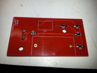
Some changes are required to the pre-amplifier PCB to fit the EQ boards. See attached schematic for details.
The EQ PCB must be secured to the board to assure long term reliability and prevent intermittent connections. Hot melt glue or electronic grade RTV are recommended.
Optional Reworks:
1. I have identified a minor issue with noise injection into the CCS via the -25V supply by the LM337. See schematic for a rework to add some decoupling to the bias supply to address this.
2. Replace R7 with 47.5 ohm resistor (33.2 - 56.1 acceptable)
Here are the instructions for building and installing the EQ PCB. (Supersedes all earlier instructions)
All the parts with the exception of the capacitors can be found here: Digi-Key - Fast Add
I do not recommend substitution of any of these parts. Thin film resistors must be used.
The 0.047uF/400V or 600V, 0.022uF and 820pF capacitors are available from Sonic Craft. The caps should be matched and close to the nominal value. (< 2% if possible) I used RTX for the 0.047uF, TFT for the 0.022uF/200V, and a polystyrene and foil for the 820pF.
Some changes are required to the pre-amplifier PCB to fit the EQ boards. See attached schematic for details.
The EQ PCB must be secured to the board to assure long term reliability and prevent intermittent connections. Hot melt glue or electronic grade RTV are recommended.
Optional Reworks:
1. I have identified a minor issue with noise injection into the CCS via the -25V supply by the LM337. See schematic for a rework to add some decoupling to the bias supply to address this.
2. Replace R7 with 47.5 ohm resistor (33.2 - 56.1 acceptable)
Attachments
I'm not exactly sure what you are doing with the solid state relays, please explain.
One thing you can try is large ferrites on the compressor power cord pretty close to the pressure switch, this should help both radiated and conducted HF harmonics during switch closure. The other thing you can do is get some snubbers (RC network designed specifically for this purpose) and install them across the switch contacts.)
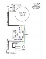
Kuzma suggests to use long wire and solid state relay for their airline arm. Please the diagram. Basically, they use solid state relay to replace mechanical contact. They use one solid state relay on the pressure switch. I tried it. But it didn’t work. So, I tried to use two solid state relays on AC power, one for phase and one for neutral. Bot relays are triggered by external 12 V DC. I am also using a long extension cord for the compressor. But nothing works.
I also tried a high current power isolator. But, the compressor motor doesn’t work with the power isolator.
Attachments
I would restore the compressor to stock and implement the suggestions I made and see where that gets you.
Since mains voltage is involved caution is required.
Check to make sure that the compressor is not plugged into a remote outlet on the same circuit as the stereo.
Since mains voltage is involved caution is required.
Check to make sure that the compressor is not plugged into a remote outlet on the same circuit as the stereo.

R20 is only changed if you cannot adjust the current to the proper value of 4mA at the cartridge. Really more important is whether you can get the currents to match closely, otherwise is not too critical as long as the current is within about +/-5% of the recommended 4mA.
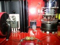
Is C2 0.047uF? Looks way too large, this is a pretty critical value with the new EQ card. (Looks like 0.068uF which is borderline acceptable, but I would recommend replacing it.)
Is C2 0.047uF? Looks way too large, this is a pretty critical value with the new EQ card. (Looks like 0.068uF which is borderline acceptable, but I would recommend replacing it.)
Is C2 0.047uF? Looks way too large, this is a pretty critical value with the new EQ card. (Looks like 0.068uF which is borderline acceptable, but I would recommend replacing it.)
No. It is 0.022 uF. Thank you, Kevin.
Kevin,
I am in the final stage of finishing up the phono. Before I do this, I want to make sure that I understand power connections correctly. Please see the image to check if everything is ok. Hopefully, I will have time to listen the system next weekend.
Where should I connect the ground of phono cable?
Thank you!
Jim
Attachments

Last edited:
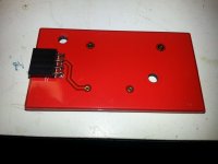
I would use the ground closest to the 300V connection rather than the one at the -24V supply.. Reverse the filament connections.
The inputs are connected to the two pads labeled "input" and are isolated from the chassis and each other. (Nothing common between the channels)
There are several ways to handle the main power an audio grounds. The way least likely to cause ground loops is to have one central ground for PSU and audio ground - this point also connects directly to the chassis. Bring the PSU gnds (nearest pads to the 300V) to the common point, bring the output RCA grounds to the common point. You can also just wire the output jacks directly to the pads provided for that purpose. I have not had an issue doing that because of the way the rest of the system is designed. (You probably won't either)
Yes.. Also swap filament connections. (+ to left, - to right)
And I was talking about C2 on the pre-amplifier PCB, not the EQ card. It appears to be 0.068uF, and needs to be changed to 0.047uF..
You can listen to it that way but the bass will be accentuated.. I would not use a clarity cap in that location, I would use a REL RTX or similar.
And I was talking about C2 on the pre-amplifier PCB, not the EQ card. It appears to be 0.068uF, and needs to be changed to 0.047uF..
You can listen to it that way but the bass will be accentuated.. I would not use a clarity cap in that location, I would use a REL RTX or similar.
Yes. These are 0.068 uF on phono boards. I will order 0.047 uF to replace them. Thank you again!
Yes.. Also swap filament connections. (+ to left, - to right)
Did you mean 6.3V?
Compressor arrived today and after getting oil everywhere filling the compressor I got it up and running very late this afternoon.
I have three filters including two coalescing filters and a motor guard filter drier as well as a low pressure regulator, and surge tank.
I started at ~7 psi and am currently a tad under 10 psi, which seems the point of diminishing returns..
The compressor runs much more frequently than I expected so I suspect a big leak somewhere still. I had expected it to run once about every half hour or so, and this might also indicate that my simplistic expectations based on Boyle's gas law (volume/pressure law) was a bit optimistic. Duty cycle is quite low so I am not worried about compressor life.
No electrical popping, but I am motivated to find another place for it, 30dBA with the frequent cycling and blow off valve...
Silentaire uses three kinds of motors. They are 1/5, 1/3 and 1/2 HP. Mine is 50-TC which has 1/2 HP. I guess mine makes the loudest popping noise. Kuzma uses 20A which has 1/5 HP motor. So, the noise may not be as loud as mine.
My compressor runs about 8 mins and stops for about 12 mins at 80 psi. I added a 10 gal tank so it extends the down time a little. I also use two computer fans to reduce the motor temperature.
You only use 10 psi. However, the maximum pressure setting on/off interval is between 25 psi and 30 psi. I think this is why you feel the running cycle is shorter than you expected. If I were you, I would reset cut-in pressure and cut-out pressure lower than default setting. It may extend motor life.
Yeah, the DR-150 has a 1/5HP compressor with 1 gallon tank.. The cut out pressure is 114 psi and cut in at around 85 psi. Reducing the cut in pressure significantly would result in only a couple of minutes of additional time and the compressor would run a lot longer. So I am going to leave it alone for now, also unauthorized tampering with the pressure switch voids the warranty..
I have absolutely no popping issue with this compressor, so I suspect you are not on an electrically isolated circuit or there is some other problem. My system also is not very susceptible to line transients.
The higher pressure does make a significant difference, but I find 7 - 8 psi is a reasonable point, above this there is enough air flow through the bearing for noise to be noticeable and it applies force to the arm pedestal as it approaches the bearing housing which isn't good.
There is a Panasonic EPC-465CR on eBay right now for BIN $99 USD
This is the low compliance end of the strain gauge family and is best suited to high mass arms. Minimum tracking force of 4gms. This will work well on arms that are suitable for M3D, early SPUs and similar.
The OEM Shibata is not a good match for this, the Bliss Shibata works well as does the OEM conical.
EPC-465C 4CH Phono turntable Cartridge | eBay
Stylus Cleaning
If your vinyl hygiene is as bad as mine you might want to remove the stylus periodically and gently brush the coupler with a fine camel hair brush, follow up by brushing the ends of the transducers very carefully.
I have cats and house rabbits as well as dust problems in the man cave in the winter and despite my best efforts I am not able to deal with it effectively - heavy winter clothing and low humidity greatly exacerbate the problem.
The dust motes and hair work their way between the coupling and the transducers over time and you will know when it happens because one or the other channel will start to distort rather badly.
- Home
- Source & Line
- Analogue Source
- Playing With Panasonic Strain Gauge Cartridges (And A Dedicated Phono Stage)