ok - if there's no cathode R on the gain stage then this is one of Bruce's fixed bias or grid leak schemes - I had some of Bruce and Scott's custom preamps which ran bias supplies
Correct it is a fixed bias setup.
Upon further analysis -1.3v at the grid will bring plate voltage down close to 100v and about 1mA of current with a 300v supply.
6EM7 voltage reference to ground should look something like
Pin 1) 104v
Pin 2) 300v
Pin 3) 135v
Pin 4) -1.3
Pin 5) 104v
Pin 6) 0v
Correct it is a fixed bias setup.
Upon further analysis -1.3v at the grid will bring plate voltage down close to 100v and about 1mA of current with a 300v supply.
6EM7 voltage reference to ground should look something like
Pin 1) 104v
Pin 2) 300v
Pin 3) 135v
Pin 4) -1.3
Pin 5) 104v
Pin 6) 0v
That looks about right, but of course, it's not what I have. Pin 5 is 300, Pin 4 is well over 5.
I can tell you this. Every component is now new. I even rebuilt the feedback network. As I said, the voltage for the grid is fine on the regulator output, but between the 2 meg and 20 resistor it gets to about 5 and is over 5 on pin 4. One clue may be that the regulator voltage itself is set almost immediately, even with low voltage from the variac. This excessive grid voltage comes up slowly like a regulated power supply powering up.
My big question is where is it coming from? I thought it might be from the raw DC on the regulator, but I find no shorts to that source nor any other source I can think of. It's not from the filaments because I use positive voltage there.
Attachments
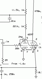
Thanks, everyone. I didn'ty realize others had joined in. I was going to update tomorrow, but I'll do so now. Yes, this is fixed bias. The regulator is a mod. One discovery. I disconnected the 20K resistor to the grid where all the voltage is. I ran up the power enough to get a good reading. About -3v on the grid. The reading on the disconnected 20K is 1/3, as expected from the regulator. Later I removed the tube with the regulator still disconnected. Reading on the grid is 0. Something in or through the tube is putting that voltage there. (Reminder: I've swapped tubes. Socket is new. More exploring tomorrow.
Solved! Once I realized the problem was that the grid was getting negative voltage from somewhere , I realized I had to widen my search from the tube in question, focusing on the previous stage. There I found a broken connection. So simple, yet it too me so long to realize that was where I should have been looking. Thanks to everyone. Next move is to get a fan to cool this thing. It runs pretty hot.
Solved! Once I realized the problem was that the grid was getting negative voltage from somewhere , I realized I had to widen my search from the tube in question, focusing on the previous stage. There I found a broken connection. So simple, yet it too me so long to realize that was where I should have been looking. Thanks to everyone. Next move is to get a fan to cool this thing. It runs pretty hot.
Congratulations, troubleshooting is tricky without a schematic. If it's really that hot, you should arrange for the fan to blow cool air on it, rather than draw hot air off it. The fan will work better and last longer that way.
- Status
- This old topic is closed. If you want to reopen this topic, contact a moderator using the "Report Post" button.