I am building a pre-amp that I want to allow changing between two different B+ voltages with the change of the 2 VR tubes. I need to also change the 4 plate resistors from 47K to 33K and I'd like to do that without opening the chassis. Can I switch in a parallel resistor, as illustrated, without loss of fidelity?
I believe my calculation is correct but I'll double check before building.
 [/IMG]
I believe my calculation is correct but I'll double check before building.
Typically for other builds I use these Carling Mini-switched:
https://www.amplifiedparts.com/sites/default/files/associated_files/p-h543_specs.pdf
https://www.amplifiedparts.com/sites/default/files/associated_files/p-h543_specs.pdf
Aren't switches usually rated at something like 250volt?
The two voltages I'm considering are 210VDC and 150VDC.
But that is one of the reasons I'm asking.
I think breaking switch contacts at high voltage dc is compounded by avoiding an arc, hence why dc switch rating has to be so conservative. But in this circuit arc current is limited by high series R so good chance of practical success. But the switch will be at B+ so whether it is safely isolated is another matter...?
I will NOT be switching at high voltage. Amp will be off when I change things. Not trying to do iy6on-the-fly. I just want to avoid opening the case and soldering .
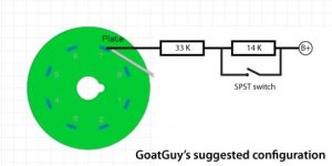
The only thing I — as a latecomer — would recommend would be to make it a series-shorting configuration instead. 33 kΩ from plate to switch; across switch a 14 kΩ resistor; and from that to B+. The switch shorts out the 14 kΩ resistor, reducing overall resistance.
KodaBMX's quip about a 50¢ switch is exactly right.
Doesn't need to more than protect you, and of course not short to chassis.
⋅-⋅-⋅ Just saying, ⋅-⋅-⋅
⋅-=≡ GoatGuy ✓ ≡=-⋅
KodaBMX's quip about a 50¢ switch is exactly right.
Doesn't need to more than protect you, and of course not short to chassis.
⋅-⋅-⋅ Just saying, ⋅-⋅-⋅
⋅-=≡ GoatGuy ✓ ≡=-⋅
if you move the switch to the other side of the 110k resistor, it'll see a lower voltage when current is flowing. of course, when it's open, it'll have the same b+ on one side since there will be no drop thru the resistor.
Like this?The only thing I — as a latecomer — would recommend would be to make it a series-shorting configuration instead. 33 kΩ from plate to switch; across switch a 14 kΩ resistor; and from that to B+. The switch shorts out the 14 kΩ resistor, reducing overall resistance.
KodaBMX's quip about a 50¢ switch is exactly right.
Doesn't need to more than protect you, and of course not short to chassis.
⋅-⋅-⋅ Just saying, ⋅-⋅-⋅
⋅-=≡ GoatGuy ✓ ≡=-⋅

The only thing I — as a latecomer — would recommend would be to make it a series-shorting configuration instead. 33 kΩ from plate to switch; across switch a 14 kΩ resistor; and from that to B+. The switch shorts out the 14 kΩ resistor, reducing overall resistance.
KodaBMX's quip about a 50¢ switch is exactly right.
Doesn't need to more than protect you, and of course not short to chassis.
⋅-⋅-⋅ Just saying, ⋅-⋅-⋅
⋅-=≡ GoatGuy ✓ ≡=-⋅
Thank you.
Be careful about using switches for HV that have silver plating on the contacts. Silver migration can become an issue over time.
Yes, but HV isn't H in this case. Perhaps 25 to 35 volts. And over time is also expected limited: this is an A/B test setup configuration.
Last edited:
Another related question. I calculate I have to dissipate over 3 watts per plate. It is hard to find 7 watt or higher rated metal film in the values I need. Wirewounds are easy to source but are they a good choice for plate resistors? What else might work? I know I can parallel some values but even two 3 watt resistors are under spec.
A 47 kOhms resistor needs a voltage of 375 V to dissipate 3 watts, a 110 kohms one even 575 V. Is the voltage drop over them really that high? Plate dissipation and plate resistor dissipation are quite different pairs of shoes.
Back to your 1st question: The switch would see only the voltrage drop over the 47 k plate resistor before it is going to be closed and even less when it is opened. Arcing will be completely prevented by the 110 kohms resistor. Hence, most probably a 250 Vdc part will fit.
Best regards!
Back to your 1st question: The switch would see only the voltrage drop over the 47 k plate resistor before it is going to be closed and even less when it is opened. Arcing will be completely prevented by the 110 kohms resistor. Hence, most probably a 250 Vdc part will fit.
Best regards!
- Home
- Amplifiers
- Tubes / Valves
- Plate Resistor?