Grid current is likely to be fairly small compared with anode current, so the rise in cathode current you see with the 'normal' valve is likely to be mainly due to anode current rise from second order distortion. 10-20% shift in DC conditions at full output is not unusual.thehoj said:Does it make sense that if I'm actually measuring current from cathode to ground, I'm not actually talking about purely plate current, but rather plate + grid current..? The current in reading doesn't actually seem to change until I get near / into positive grid region..
Yes, considering the symptoms, this seems to be the most likely cause. But again, without a scope, no way to check this.Grid current is likely to be fairly small compared with anode current, so the rise in cathode current you see with the 'normal' valve is likely to be mainly due to anode current rise from second order distortion. 10-20% shift in DC conditions at full output is not unusual.
I actually can't understand why one would build amplifiers without one the most basic tools. An entry level scope from Rigol costs $400 nowadays and is therefore no more expensive than a decent multimeter. Yes, Rigol is Chinese cheapware but it does the job.
Yes, considering the symptoms, this seems to be the most likely cause. But again, without a scope, no way to check this.
I actually can't understand why one would build amplifiers without one the most basic tools. An entry level scope from Rigol costs $400 nowadays and is therefore no more expensive than a decent multimeter. Yes, Rigol is Chinese cheapware but it does the job.
Well, though I haven't mentioned it in this thread. I do have a Philips scope. It's not great, and I can't seem to figure out how to get any successful measurements of a lot of the stuff I feel like I should be able to.
I've been using it to view the sine wave waveform over a resistive load on the output of the amplifier.. So that's how I know that I have a 48Vp-p 1Khz sine wave over an 8 ohm resistor on the output of the amplifier just before clipping.
At one point you said you really need to use a scope to see the waveform, in particular to see the DC and AC components
I don't really know where / how you're suggesting that I should make that measurement with the scope..
There are many things that may be wrong.At one point you said you really need to use a scope to see the waveform, in particular to see the DC and AC components
I don't really know where / how you're suggesting that I should make that measurement with the scope..
- Your mosfet driver may not provide enough current to drive the grids of the output valves and the signal gets clamped.
- The output stage develops high distortion as pointed out by DF96
- ...
Posting the schematic would also help.
There are many things that may be wrong.
Without seeing the waveforms (cathode/grid current/voltage), we can't give advice. I'd start with the driver and check if it's sufficient in a worst case scenario.
- Your mosfet driver may not provide enough current to drive the grids of the output valves and the signal gets clamped.
- The output stage develops high distortion as pointed out by DF96
- ...
Posting the schematic would also help.
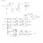
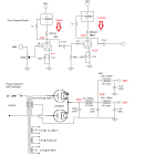
I'm attaching schematics.
The fact that one 845 seems to work as expected regardless of position in the amp makes me think that the mosfet driver is configured okay. I think it's just the one 845 that I'm having an issue with.
The driver can produce 400Vp-p very cleanly, measured on my scope with 2Vp-p 1Khz sinewave on the input.
When using the 845 power tubes I use #56 tubes in the first stage of the driver. When using 211 power tubes I use #27 tubes in the first stage. With #27 tubes in, I max out at 240Vp-p, with #56 tubes in, I max out at 400Vp-p. The 6BL7 stage stays in place regardless of which tubes are in the first position.
The driver and power stage are in separate chassis', to make the amp more manageable size wise.
When using either 845 or 211 tubes biased at ~80mA I get up to ~48Vp-p over an 8 ohm resistive load (using the 8ohm taps on the output transformers), and just up to ~33Vp-p over a 4 ohm resistive load (using the 4ohm taps on the output transformers) with a 1Khz sinewave just before the sinewave starts to clip on the bottom of the waveform. This happens for both the 211 and 845 tubes before the driver runs out of steam. So I don't think there is any issue with what the driver stage is producing.
I kind of think I'm going around in circles here.. The original purpose of my thread was to try and determine if I have an issue with one of my 845 tubes. In my mind one of my 845 tubes is working as I expect it to.. And both of the 211 tubes I have are also working as I expect.
So to be honest I'm not exactly sure what I'm trying to determine here anymore.. lol. I think it seems pretty clear that the one 845 is drawing excessive current in one way or another, and because it happens regardless of which channel I use that 845 in, it definitely seems to be tied to that tube, not the driver or supporting circuitry for either channel.
I guess it probably would be good to measure waveforms as you suggest at the cathode and grid. Are you suggesting measuring the signal waveform at the gate of the mosfet, and then also at the grid of the power tube / source of the mosfet?
Attachments
Last edited:
The most straightforward way to measure grid current is with a current probe attached to the scope, but few of us have access to current probes. It's not unreasonable to make a simple ad hoc current transformer for jobs like this -- a DIY current probe. Here's one way to go about it: AC Current Probe
Another way, if the scope allows, is to insert a current sampling resistor, probe both ends with voltage probes, and subtract one channel from the other. Isolated differential voltage probes are available on the market, but prices aren't much lower than current probes.
Another way, if the scope allows, is to insert a current sampling resistor, probe both ends with voltage probes, and subtract one channel from the other. Isolated differential voltage probes are available on the market, but prices aren't much lower than current probes.
Does it make sense that if I'm actually measuring current from cathode to ground, I'm not actually talking about purely plate current, but rather plate + grid current..? The current in reading doesn't actually seem to change until I get near / into positive grid region.. On both tubes, it's just one of the tubes is drawing more than the other.
For 845s, that's normal. See the spec sheet: it confirms that this type begins pulling grid current at ~VGK= -5.0V and even recommends not exceeding that with the signal. Back then, they didn't have source followers either.
As for the 845 that seems to "run away", suspect it's gone slightly gassy. With fixed bias, gassy tubes don't seem to ever "settle down".
Gas seems like a reasonable explanation for that errant 845s behavior, and would be consistent with running at zero bias for even a short period where localized overheating may have liberated trapped gas - perhaps more than the getter can handle.
Thanks for the info guys.. I think I'm gonna order a set of these Grant Fidelity sponsored 845B's.. 1. 845B Select (pair) | Psvane & Shuguang Treasure Audio Tubes
Seems like a good price, and good quality control on these ones.
Seems like a good price, and good quality control on these ones.
- Status
- Not open for further replies.
- Home
- Amplifiers
- Tubes / Valves
- plate current variation with fixed bias