Pioneer sw8-mk2. This my first time attempting a repair on a board. Before you tell me this amp isn't worth the effort, let me say my goal is to learn to repair stuff and if I end up with a usable amp that will be a bonus.
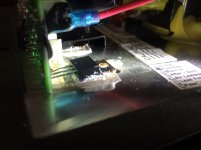
Visual inspection - fuse blown and one component is separated from the plate where a conductive grease had been applied. I see a hole in the plate next to the component, was there once a screw or clamp there perhaps?
I assume I don't want to put a new fuse in and plug it in.
The component has three legs. I don't know what tests to perform. I checked and there is continuity between the outer legs, but without even knowing what the component is, it means nothing to me.
Attachments
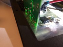
The semi-translucent material between the transistor and the chassis is a mica insulator. By installing that screw like you did you defeated the whole purpose of the insulator. There needs to be a nylon shoulder washer between the head of the screw and the transistor. Without screw installed and it still blows the fuse you have bigger problems than a missing screw.
Craig
Jon beat me to it.
Craig
Jon beat me to it.
I didn't see the replys until after I made a clamp. There are numbers but I have to buy a loop to see them. I'll go get one and post the numbers in a bit. Thanks for your help.
Looking at the pic it looks like the mica slid and the tab might be making contact. I'll check that. There is nylon around the screw so it is not touching the tab.
Looking at the pic it looks like the mica slid and the tab might be making contact. I'll check that. There is nylon around the screw so it is not touching the tab.
Attachments
Last edited:
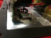
irf9530
y37k
a0
here is a link to the datasheet: http://www.irf.com/product-info/datasheets/data/irf9530.pdf
I'll see if I can figure out how to test it with my multimeter
If it was running unclamped it wouldn't take long to cook it I suppose.
y37k
a0
here is a link to the datasheet: http://www.irf.com/product-info/datasheets/data/irf9530.pdf
I'll see if I can figure out how to test it with my multimeter
If it was running unclamped it wouldn't take long to cook it I suppose.
Last edited:
OK those are MOSFETS, looking at the face with the pins towards you, pin1 is on the left and pin 3 is on the right. Pin 1 is the Gate, Pin 2 is the Drain, and Pin 3 is the Source. You should have no continuity between Pins 2 and 3, if it reads ZERO it's shorted. Yes if the amp was run for any length of time they are probably fried. Make sure you check the other one also and always replace in pairs.
It may not matter to you at this point but there are several cheap sources of IRF530/9530 and similar audio-compatible mosfets, who supply parts with an "N" suffix, as in IRF530N, 9530N. These types are modified for switching applications and despite assurances, they aren't as good for audio as the original type. Chinese suppliers usually ignore the difference and even their own advertising by sending you the switching type regardless. Watch that any local source isn't just reselling the N type too.
Thanks. I started a thread in the 'parts' forum before buying them today. These are what I ended up ordering:
IRF9530 Vishay / Siliconix | Mouser
IRF9530 Vishay / Siliconix | Mouser
- Status
- This old topic is closed. If you want to reopen this topic, contact a moderator using the "Report Post" button.
- Home
- Amplifiers
- Solid State
- Plate amp repair question