I'm putting together a DAC design that's also a master clock generator for incoming digital sources, in hope of eliminating the jitter concerns associated with having to sync with an incoming clock otherwise.
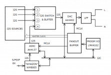
The DAC will be equipped with 4 I2S input ports and a mux-buffer. Three for sources that can be sync-ed with a master clock, one for those can't be.
A clock generator and a fan-out buffer provide with three copies of master clock. One for the operation of the DAC itself, one for ASRC, another for sync-able I2S sources. A programmable ultra low jitter xosc is used as the frequency source.
As of sync-able I2S sources, I don't have a clear idea about exactly how and what to implement at this point of time. Perhaps an XMOS that takes external MCLK? Perhaps a RPi hat that takes external MCLK? I leave that part open for now. So the DAC board will have a MCLK breakout port in differential form, and three I2S input ports made up with 9 U.FL connectors. The differential clock signals can breakout with either a pair of U.FL cables or a SATA data cable common for internal hard drive in a desktop PC.
For sources that can’t be sync-ed with a master clock, such as CD transports, Ethernet streamers, or any sources in Spdif form, we have an ASRC for them. They could be handled with a Spdif receiver first, my other project called “Whazon” will do, where they get mux-ed, decoded, and forwarded through I2S into the ASRC, which is clocked with one of the copies of the same master clock that clocks the DAC.
Major devices:
DAC: AK4493
ASRC: AK4137
XOSC: LMK61E2 or Si570
CLK Buffer: Si53307
LDO: LP5907 x many
Vref: LT3042
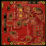
The PCB is a 4-layer construction, 10cm x 10cm in size. The area around the AK4493 closely follows AKM’s EVAL board layout.
The DAC will be equipped with 4 I2S input ports and a mux-buffer. Three for sources that can be sync-ed with a master clock, one for those can't be.
A clock generator and a fan-out buffer provide with three copies of master clock. One for the operation of the DAC itself, one for ASRC, another for sync-able I2S sources. A programmable ultra low jitter xosc is used as the frequency source.
As of sync-able I2S sources, I don't have a clear idea about exactly how and what to implement at this point of time. Perhaps an XMOS that takes external MCLK? Perhaps a RPi hat that takes external MCLK? I leave that part open for now. So the DAC board will have a MCLK breakout port in differential form, and three I2S input ports made up with 9 U.FL connectors. The differential clock signals can breakout with either a pair of U.FL cables or a SATA data cable common for internal hard drive in a desktop PC.
For sources that can’t be sync-ed with a master clock, such as CD transports, Ethernet streamers, or any sources in Spdif form, we have an ASRC for them. They could be handled with a Spdif receiver first, my other project called “Whazon” will do, where they get mux-ed, decoded, and forwarded through I2S into the ASRC, which is clocked with one of the copies of the same master clock that clocks the DAC.
Major devices:
DAC: AK4493
ASRC: AK4137
XOSC: LMK61E2 or Si570
CLK Buffer: Si53307
LDO: LP5907 x many
Vref: LT3042
The PCB is a 4-layer construction, 10cm x 10cm in size. The area around the AK4493 closely follows AKM’s EVAL board layout.
Attachments

Sorry to say so, but it sounds like another 'me too' dac from the DIY community. What the DIY community seems to have missed entirely can be done with ESS or AKM dac chips. The two examples of commercial products that have gone to the next level are from Benchmark and Crane Song. One uses ESS and the other AKM. What they have in common that nobody else does is external interpolation filtering offloaded to an ASIC and prior to that upsampling everything to 211kHz (possibly using SRC4392 with a 27MHz clock).
Of course, attention still has to be paid to all the stuff the DIY community already knows about, things like minimizing jitter and, super-clean power quality, and very carefully designed output stages. But, one can only get so far with those things while ignoring other things. Small improvements to what everyone else is already doing pretty well isn't what primarily separate out the best dacs from the close runner-ups. The biggest difference there is what the runner-ups ignore completely.
Of course, attention still has to be paid to all the stuff the DIY community already knows about, things like minimizing jitter and, super-clean power quality, and very carefully designed output stages. But, one can only get so far with those things while ignoring other things. Small improvements to what everyone else is already doing pretty well isn't what primarily separate out the best dacs from the close runner-ups. The biggest difference there is what the runner-ups ignore completely.
Sorry to say so, but it sounds like another 'me too' dac from the DIY community. What the DIY community seems to have missed entirely can be done with ESS or AKM dac chips.
This is what I am looking for...
A main difference is that I would like to do my own PCB boards and have this under the same hood as my amplifiers. Most layouts to me are not well organized and I want my system with only a data, power and speaker connectors. None of this mismatched and pieces and wires everywhere..I am lead to believe that the ESS is capable of up to 8 channels.. I would be interested in 2 channel at first and then followed by a 3.1 setup. It'll happen, when is the only question.
Thoughts?
S
Sorry to say so, but it sounds like another 'me too' dac from the DIY community. What the DIY community seems to have missed entirely can be done with ESS or AKM dac chips. The two examples of commercial products that have gone to the next level are from Benchmark and Crane Song. One uses ESS and the other AKM. What they have in common that nobody else does is external interpolation filtering offloaded to an ASIC and prior to that upsampling everything to 211kHz (possibly using SRC4392 with a 27MHz clock).
There is nothing revolutonary about external filters or ASRC's. Such dacs, commercial and diy, have been around since the mid 1990's.
There is nothing revolutonary about external filters or ASRC's. Such dacs, commercial and diy, have been around since the mid 1990's.
Sure. That does not change the need to seriously consider doing such things with the latest chips from ESS and AKM, which almost nobody does.
I would be interested in 2 channel at first
In stereo mode ESS have a 16 mA output current and you need firstly to design I/V converter with appropriate specs.
Not to say they are nonrealistic, but you will need to achieve -120 dB being loaded to 3V/0,016A =~200 Ohms. I’ll prefer external heatsink (not board level, ~3 Wt/channel) and at least ~50-70 mA converter idle current.
Next, being concerned about MCLK jitter you’d better first to decouple grounds and designing low-impedance high-frequency supply regulator. External signals are better to input via ones-of-picofarad isolation barrier or level converter. Of course, MCLK output must be decoupled from board and buffered, external digital devices doesn’t need so precise clock.
Hi,
Are you sure that the ESS chips are true current output chips? That they perform better in "current mode"?
I ask this because I get the impression that they (ESS) included the "feature" to please the people who think current output chips are better, and not necessarily as an improvement over voltage output which to me seems the real operating mode of these chips (voltage output with a highish output impedance, 200 ohms according to your post).
BTW, I heard this from more experienced and in the know people.
Thanks
Alex
Are you sure that the ESS chips are true current output chips? That they perform better in "current mode"?
From what I've read about ESS DACs seems they're resistors inside, fed from a reference voltage (AVCC) in a potential divider. So neither true voltage output (low impedance) nor true current output (high impedance). The measurements are better when the output terminal doesn't vary its voltage with signal due to some (small) voltage coefficient of the resistors inside.
Based on the very recent experience of Allo with their Katana, I'd say a LPF prior to the I/V converter might be a good idea for those concerned not just with the numbers.😛
Richard, I think your circuits are good (lpf before the active stage). Especially with dacs that tolerate some voltage swing on the output pin, because there will obviously be some (in the pass band of the filter). I have to build one of your circuits.
Thanks
Alex
Thanks
Alex
Actually, not just in the pass band... High frequencies will also swing the voltage at the dac output pin, right? Because of the inductors. Did you by any chance measure the waveforms at the TDA1387 output pin?
It could very well be that a little filtering coming right out of the dac and before the I/V stage would be good. However, some uncertainty about what exactly would be the best approach. Probably have to cut and try to some extent, with a lot of measuring and listening to make sure it is doing more good than harm. Someone please let me know when you have finished the research, we all would love to see it. Probably, ESS would too.
Actually, not just in the pass band... High frequencies will also swing the voltage at the dac output pin, right? Because of the inductors. Did you by any chance measure the waveforms at the TDA1387 output pin?
Hopefully its not too OT to mention some details about passive LPF filtering. There is some peaking (seen in LTSpice simulation) which depends on the Q of the filter. Its been under 6dB on the filters I've so far designed and its at a maximum around the corner frequency of the filter. However the 6dB boost means the characteristic impedance of the filter (which I keep under 100ohms in my circuits) goes up to at most 200 ohms. So still well within the compliance range of the DAC.
Using an LC filter when the source impedance is much lower (as here, my 1387s are pure current source output) will only result in similar peaking if the load impedance is also considerably lower. In simulation I find a 100:1 ratio of source to load is indistinguishable from a pure current source as source. Hence I'd recommend a target load impedance with an 800ohm source (DPH's mentioned that's the Z-out of the q2m) around 8ohm or so.
Richard, I got it, thanks for the detailed answer.
What is relevant to the thread, is that a filter which is around 100 ohms impedance in the pass band, peaking at 200 ohms in the transition band, is not suitable for the pcm1704, because it is known that the chip needs a very low (20 ohms?) impedance at the output pin to give its best.
With other dacs I agree that it works well, particularly with the 1387, which I found to sound good even with a 1800 ohm resistor as I/V converter.
About the filter with 8 ohm impedance, I imagine the capacitor values will get quite high making it difficult to construct.
How did PCM1704 get into the thread? I only see the OP mention AK4493 which I guess is voltage out? I'd not recommend LC passive filters with voltage out DACs, the impedances tend to be too low.
You're right about needing high value caps with low impedances. I don't find too much degradation from using X7Rs in such filters though....
You're right about needing high value caps with low impedances. I don't find too much degradation from using X7Rs in such filters though....
- Status
- Not open for further replies.
- Home
- Source & Line
- Digital Line Level
- Planning on a jitter concern-free DIY DAC