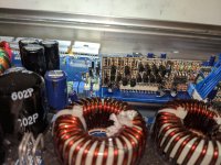
Some background on the amp. I've had it sitting on a shelf for 5 years and finally decided to fix it and get it gone. It had 3 blown IRFZ46N PS FET's and 2 blown IRFB31N20D's. Per Perry's writeups on this amp/similar amps, I went through all the common items. I upgraded the power supply FET's to IRF3205's with 47 ohm gate resistors. I insulated all output inductors and transformer windings. I checked the output caps and they are still good. After replacing the PS FET's with no output FET's installed, I have solid +/- ~75V rails. I preemptively replaced Q124 and Q125 on the driver card based on recommendation. I also did NOT install the output FET's and instead placed a 1nF cap from gate to source on one high side bank and one cap on the low side bank. I wanted to check the drive signals per recommendation also. My drive signals at the gate looked good on the low side and the high side has good amplitude, but with a 5V offset when driven with a 100hz signal. Post #21 here had the same thing: https://www.diyaudio.com/forums/car-audio/328485-ground-zero-amplifier-repair.html
So the main question I have has to still do with the driver card. I don't want to install the output FET's until I know everything else is working right. When I am in this configuration, Q116 and Q118 get scorching hot. Q116 gets to 150C and Q118 gets to 109C after 30 seconds of being on. I don't know if that is just because of the driver not being run properly with output FET's for feedback, or if I still have a problem. I have replaced Q116 and Q118 with no change. I have checked R174 (10k) and D114 (5.6V zener). I have pulled Q126 and Q127 and no change also (besides the expected bad drive signal). The only thing left after Q116 and Q118 is the freshly replaced Q124 and Q125 transistors along with 2 resistors that test fine. What else can I be missing or is this normal? I know these drivers run hot, but that seems way too hot.
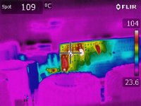
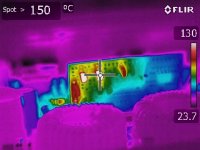
So the main question I have has to still do with the driver card. I don't want to install the output FET's until I know everything else is working right. When I am in this configuration, Q116 and Q118 get scorching hot. Q116 gets to 150C and Q118 gets to 109C after 30 seconds of being on. I don't know if that is just because of the driver not being run properly with output FET's for feedback, or if I still have a problem. I have replaced Q116 and Q118 with no change. I have checked R174 (10k) and D114 (5.6V zener). I have pulled Q126 and Q127 and no change also (besides the expected bad drive signal). The only thing left after Q116 and Q118 is the freshly replaced Q124 and Q125 transistors along with 2 resistors that test fine. What else can I be missing or is this normal? I know these drivers run hot, but that seems way too hot.
Attachments
Unless you checked the flir against a contact thermometer on an object with the exact same surface, the readings may not be reliable. The readings can be skewed greatly by surface color and texture.
Where's the fan?
If you install a fan and mount the drivers well off of the board (almost touching the fan blades), how much does the temperature come down?
You can get higher velocity fans (about 10cfm) and for amps that use good cores that run cool, you can turn the fan blowing to the board, not to the inductors.
Unless you checked the flir against a contact thermometer on an object with the exact same surface, the readings may not be reliable. The readings can be skewed greatly by surface color and texture.
Where's the fan?
If you install a fan and mount the drivers well off of the board (almost touching the fan blades), how much does the temperature come down?
You can get higher velocity fans (about 10cfm) and for amps that use good cores that run cool, you can turn the fan blowing to the board, not to the inductors.
Thanks for the reply.
I checked the FLIR image both covered in kapton tape and not covered with same results. I don't think it is an emissivity problem on the FLIR. I can check with a different thermometer, but I'm fairly confident in the FLIR readings. The deltas between the other parts should all be accurate too being the other transistors are the same color/case as the ones in question so that means the other parts are running much cooler.
I have an upgraded fan (Delta AFB0412HA-A), it is just not installed into the board while I do this initial checkout so I have easier access to the driver components. I plan to have it blow on the driver and I have already mounted Q124 and Q125 so they will be much closer to the fan blades when the fan is installed. I figure for keeping it on for a minute at a time to check things out should not cause failure, especially when I don't plan to drive the amp hard until I have everything properly installed. I am just trying to make sure I don't have something else going on because of the large temperature delta of Q116 and Q118 compared to the rest of the driver board.
Do you have a reference that tells you that those transistors are running hotter than normal? I don't know if I've checked those but I have checked others on that board and they were about 290F without the fan.
Do you have a reference that tells you that those transistors are running hotter than normal? I don't know if I've checked those but I have checked others on that board and they were about 290F without the fan.
I do not have reference that says they do or do not run hotter than normal. Most of my info on this board comes from your generic class d 2 page and another forum member who reverse engineered these driver cards. If my temps are normal is what I am trying to determine. I do not have a known good reference to check against. I just know that 150C is really hot and usually not good from a semiconductor lifetime standpoint. If other components were 290F, which is around 143C, then it might not be out of the range of normal. If that is in fact the case, I'm happy that mine might be "normal" but also wary that it still borders on too hot.
If mine is in fact "normal," I could probably comfortably put the outputs back in and check operation. I would be running it on a current limited supply initially so hopefully that would catch any catastrophic failures.
Q124/125 are the ones that were 291F. With them mounted to within about 1/16" of the fan blades, they ran about 100 degrees cooler withthe fan running. Q124 and 125 run hot enough to cook the solder and the board to a point where the board has to be cut away to be saved.
Q124/125 are the ones that were 291F. With them mounted to within about 1/16" of the fan blades, they ran about 100 degrees cooler withthe fan running. Q124 and 125 run hot enough to cook the solder and the board to a point where the board has to be cut away to be saved.
I figured Q124 and Q125 were what you were referring to based on their high failure rate. Any component that hot "as designed" implies some of those adjacent parts could also be that hot. My board did not have signs of total abuse/burning, so I think it is still workable. Unless you think otherwise, I'll install the outputs along with the fan and check things again.
If the drive signals are good, install the outputs, clamp them and test. If the drive signals are good, I doubt that there will be any problems.
If the drive signals are good, install the outputs, clamp them and test. If the drive signals are good, I doubt that there will be any problems.
That's the hope! It just seemed like those couple transistors were running extra hot. I'll get stuff installed and report back. If I remember it, I'll take some drive screenshots.
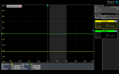
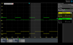
I'm working on getting the outputs installed and the fan, but for reference here is what the gates of the output fets look like with just a 1nf cap on each bank. There is a little bit of ringing on the rising edge of the high side, but I'm not sure if it is enough to be concerned or just a scope artifact. I'm using the negative speaker terminal as my ground reference with about a 6 inch cable to get to my scope probes.
One thing I do notice is that the on/off times are not symmetrical for the high side and low side, but again without the outputs in I'm not sure if that matters.
One thing I do notice is that the on/off times are not symmetrical for the high side and low side, but again without the outputs in I'm not sure if that matters.
Attachments

Last edited:
- Home
- General Interest
- Car Audio
- Planet Audio VX2200D Strange Driver Issue