Hi to all,
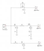
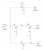
I have a question regarding whether to place resistor before or after the tweeter crossover or does it matter? Attached is Xsim screenshots which display both methods. If there is a reason for one method or the other, what might that be?
Thanks in Advance,
Rich
I have a question regarding whether to place resistor before or after the tweeter crossover or does it matter? Attached is Xsim screenshots which display both methods. If there is a reason for one method or the other, what might that be?
Thanks in Advance,
Rich
Attachments
Hi TNT,
Thanks for the reply. I had it playing that way (after the filter) but I decided to change resistor value. Thought I would ask while things were apart.🙂
Best Regards,
Rich
Thanks for the reply. I had it playing that way (after the filter) but I decided to change resistor value. Thought I would ask while things were apart.🙂
Best Regards,
Rich
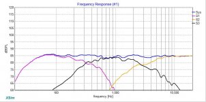
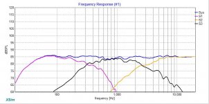
The tweeter response in Graph #1 looks to be slightly higher (around 0.5 dB).
Does XSim plot acoustic phase? If so, is there a difference there?
May or may not be noticed in listening.
Does XSim plot acoustic phase? If so, is there a difference there?
May or may not be noticed in listening.
The series resistor placed before is fine, and can significantly reduce the impedance phase variance if that matters to you. Also, when placed before, the resistor will not tilt down the tweeter response as much as if placed after.
Shunting resistors across the tweeter will reduce impedance magnitude, and give a fairly even overall cut of level without tilt.
What you don't want is the series and parallel placed both before the xover. This will yield full-bandwidth attenuation, and make the resistors run hot as they would be placed directly across the amplifier output. If you place a series resistor in either position, and a parallel resistor after the xover, then the resistors will only have to attenuate above the Fc of the xover.
Later,
Wolf
@Dave R,
Yes, Xsim does track phase. I took a quick look at differences between the two this morning and it appears to be trade offs either way. There is slightly better mid to tweeter phase tracking but horrible between woofer and mid with resistor before the Xover. With resistor after the Xover woofer to mid shows excellent phase but not quite as excellent between mid and tweeter. The best solution so far seems like 2.2 ohm resistor after the Xover. This yields least amount of parts and if lower distortion is gained (per TNT) all the better.😀
@ wolf_teeth,
I tried several combination this morning from your post and kept coming back to resistor after the Xover. By placing resistor after the Xover, I can keep all other components/values in place without the need to buy new capacitors or unwind coils to achieve the flat response I'm looking for. 🙂
Much Thanks,
Rich
Hi Lojzek,
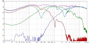
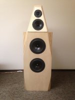
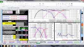
I have attached a screenshot from PCD showing coordinates I arrived at using Jeff Bagby's method to finding relative acoustic offsets in PCD. This was arrived at by actual measurements not by simulations if that matters. After that process, I then exported summed response from PCD over to Xsim and adjusted mod delay to 3.78" for woofer and -0.04" for tweeter so the overlayed lines matched up.😀 I like working in both PCD and Xsim. Also, there is attached a photo of speaker and another screenshot from REW with Xover in play. Note: this was taken using 4.5 ohm resistor in series after the Xover. I have been listening to it for about a year now and feel it needs some slight tweaking. Hopefully, I have provided you with enough information. I really appreciate you taking a look at this.😀
Best,
Rich
Attachments
It looks as if you have chosen a point of reference the midrange unit but the y coordinate for the tweeter iz zero, and if my assumption were true, tweeter should have been assigned some + distance (mid/tw ctc). Why don't you attach all measurements you have made, without crossovers. Something is unclear to me.
If you have the resistor on the tweeter side, you are driving the tweeter with a higher impedance, so this can reduce the effect of the roll off due to tweeter coil inductance at high frequency (high frequency boost). This looks more like current drive, which can reduce distortion. It will raise the Q of the low frequency resonance. With only two ohms, you will not notice any substantial effect.
Hi Lojzek,
One thing that might help to explain is the TM cabinet is sloped back 15 degrees. I'm trying to figure out how to attach my measurement files. I tried changing the file extension to .txt files and that still did not work. Any suggestions would be appreciated,
.
Best,
Rich
One thing that might help to explain is the TM cabinet is sloped back 15 degrees. I'm trying to figure out how to attach my measurement files. I tried changing the file extension to .txt files and that still did not work. Any suggestions would be appreciated,
.
Best,
Rich
Hi Lojzek,
I had to zip files in .txt form. You will need to change them back to .frd or .zma files (I'm sure you knew that) after un zipping them.🙂 I will attach nearfield measurements in next post.
Best,
Rich
I had to zip files in .txt form. You will need to change them back to .frd or .zma files (I'm sure you knew that) after un zipping them.🙂 I will attach nearfield measurements in next post.
Best,
Rich
Attachments
-
SSr2604-83300_Z+phase.zip325.5 KB · Views: 47
-
SB15mfc30_z+phase.zip327.2 KB · Views: 49
-
daytonrs225x2_Z+phase2.zip326.8 KB · Views: 49
-
SSr2604-8330+SB15mfc30_farfield.zip300.8 KB · Views: 42
-
SSr2604-8330+daytonrs225x2_farfield.zip309.2 KB · Views: 49
-
SSr2604-8330_farfield.zip285.5 KB · Views: 47
-
SB15mfc30+daytonrs225x2_farfield.zip333.3 KB · Views: 71
-
SB15mfc30_farfield.zip325.3 KB · Views: 48
-
Daytonrs225x2_farfield.zip351.2 KB · Views: 46
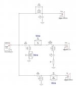
Ok Rich, I would like you to try certain mods out and tell us how that sounded to you, and these are to bypass with a piece of wire following resistors, R1=3.5; R2=2; and R4=2.2.
Hi Lojzek,
I would be more then happy to try out these mods. It may be Monday before I'm able to try this out. I do have a few questions though.
1. Is 18 gauge coil wire adequate? Have extra from unwinding a couple coils.
2. What kind of audible changes should I be looking for from each resistor? I would assume that we would bypass one resistor at a time (but maybe not).
3. What is the theory for this wire bypass modification. Inquiring minds need to know.😀
I have attached an Xsim diagram showing the bypass of the resistors. Just wanted to double check if this is what you have in mind.
Best,
Rich
Attachments
1. 18 awg is more than adequate
2. bypass all of them at once
3. the main idea was to improve the sound by increasing the sensitivity of midrange and tweeter, and summed spl at w/mid crossover point. Whether or not this becomes an actual improvement, the judge of it, you will be.
We will deal with further changes after you get this one tested, depending.
- Status
- Not open for further replies.
- Home
- Loudspeakers
- Multi-Way
- Placement of resistors in tweeter filter Question(s)