I was just given an old Pioneer SX-3700 receiver. It needed a bit of cleaning up but otherwise everything works. I do find it runs a bit hot and would like to verify the idle bias. There are not alot of pots on this thing. The only 2 sets I can see, one set looks like a power meter adjustment and the other 2 are in the tuner section. I don't think it would be wise to start adjusting any of them just to see what they do. A schematic would be nice but if someone can jut tell me which pots or even their general location, I can figure the rest out.
Thanks
BL
Thanks
BL
Hi computeruser,
Don't touch the tuner pots, ever. I don't have the schematic, but bias controls will be physically near the output transistors. You can set the bias around 10~15 mA measured across the emitter resistors. (mV / R)
Some pioneer units mounted the regulators to the main heatsink. These can run hot enough to heat up the entire assy. SX-5 as an example. Others may use an STK or STK like pak. Bias adjustment is then not possible. They may run quite warm to. Use a 'scope to ensure the unit is not oscillating if there are no bias controls.
-Chris
Chris..we meet again!
There are no pots near the output x-istors.
They are 2SA1075 NP(X) / 2SC2525 NP(X)
Odd looking package/case style
No regulators on the heatsink - its one of those
multi finned aluminium jobs that would look more at
home on a CPU cooler. Maybe these do run hotter.
The x-former is warm too after an hour so something
is drawing current.
I have not measured the idle current as it is hard to get
in there. There are lots of TP's that are hard to access
as well. To get at the control pots for cleaning I had to
take the tuner dial section off and restring it when I
put it back together - not fun. I may go underneath
to get some good contatcs.
There is little about this reciever out there (on
the net) Some of the other series have a self bias that
uses closely matched outputs. If one is off a bit
you get some heat. There is also more than I would like
DC offest - 50mv which may be a factor. I figured the
pots I could see WERE for the tuner but the layout of
this thing is odd. The diode bridge is at the front,
behind the power switch. The x-former/caps/regulator
are in the back.
The Adcom is still running. I intentionally blew one
of the witness resistors as a test. THEY CATCH FIRE!!
I'll have to get some flame proof devices for the
parts bin.
BL
I'm glad to hear your Adcom is fine. Burning resistors is fun huh?
Many newer rcvrs have the bias network done with fixed resistors. Sometimes there is a higher value in parallel that is cut or reinstalled to adjust the bias. With a nice unit (nice-ish?) I'll mess with the value to set the bias where I want it. This is very difficult to find unless you are use to finding these without a manual. Hint: The small transistor on the heatsink. Follow the traces.
-Chris
I just messed around with a SX 3800 with the same outputs, but mine had 2 pots per channel to set the bias. the pots were on the amp board that is mounted vertical and also hard to access with the regs mounted on a vertical board on the other side of the sliced fin sink. Beware of the crappy sockets on the outputs.
PS nice units they are. The 2 pots near the output meters are meter adjustments.
PS nice units they are. The 2 pots near the output meters are meter adjustments.
Thanks for the replies. Looks like the 3800
is quite different from the 3700. I may have
to get the service manual.
BL
is quite different from the 3700. I may have
to get the service manual.
BL
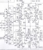
Here is the procedure from the Service Manual
Pioneer SX-3700 Idle Current Adjustment
1/ Turn volume down to minimum, turn power
power on, and wait about 10 minutes.
2/ Connect DC voltmeter to the TP terminals.
(L ch - TP48/49) (R ch TP46/47)
3/ Check that the voltage lies within 2.2mV-100mV
DC. If voltage is LESS than 2.2mV, cut jumper
A (L ch), and jumper B (R ch). If voltage
exceeds 100mV, check for circuit failure.
Attachments
pioneer sx 3700 cut wires
hey this isnt supposed to be a reply but does anybody know why there are two wires cut inside my amp. they are between the radiator fins and the front. they're two red 1" long wires with a long red one in between. and also does any body have the manual to it. it would be nice if yo ucould post it please.
hey this isnt supposed to be a reply but does anybody know why there are two wires cut inside my amp. they are between the radiator fins and the front. they're two red 1" long wires with a long red one in between. and also does any body have the manual to it. it would be nice if yo ucould post it please.
addition to question
oh yeah it works. some times when i have my old denon cd player hooked up it makes a buzzing noise through the speakers and it wont stop till you move the amp arround. Any ideas why?
oh yeah it works. some times when i have my old denon cd player hooked up it makes a buzzing noise through the speakers and it wont stop till you move the amp arround. Any ideas why?
The wires are cut as described in item #3 above, This is normal. Mine are cut too. There really are no adjustments to be made on this unit. BL
- Status
- Not open for further replies.
- Home
- Amplifiers
- Solid State
- Pioneer SX-3700 bias